
How to set 'EYE RELIEF' in a sequential optical system design?

Solved
eye relief
Best answer by David
Hello Chandan,
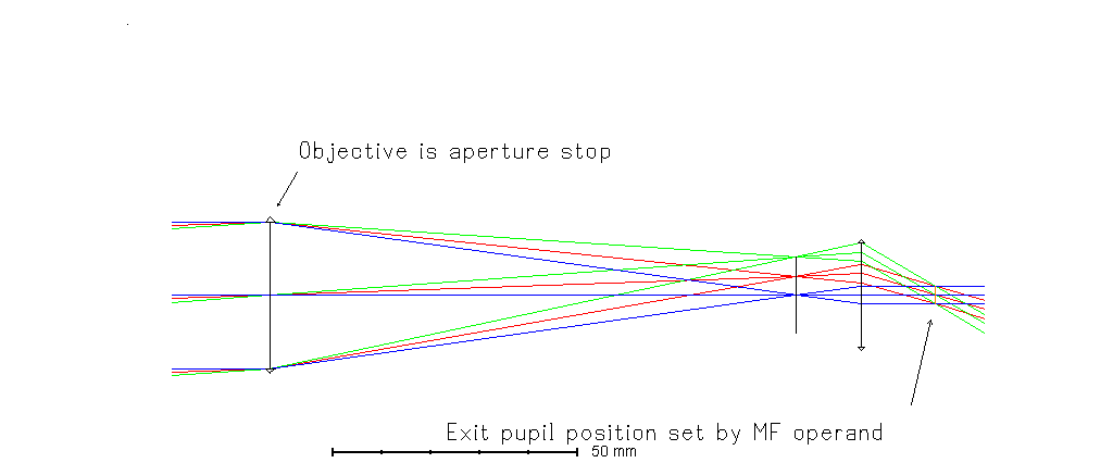
If the design is done in the forward as-used direction, then the eye relief is the distance from the last surface to the exit pupil position. The merit function operand EXPP can be used to target the exit pupil to a certain distance from the image plane, which can be used to set this distance. (EXPD can target the exit pupil diameter.)
However, it is very common to design such systems in reverse. For example consider an 8x30 binocular with an 8.3 degree full field of view and a specified eye relief of 15.1mm. In the attached ZAR the design is executed in reverse. Since the magnification is 8x, the field of view is 8.3 x 8 for a 33.2 degree maximum field angle. The exit pupil is 30mm / 8 for a 1.875mm semi-diameter.
The exit pupil diameter and the eye relief are enforced by making the exit pupil an external stop in the reversed design. This is surface 2, and the semi-diameter is fixed at 1.875 and the thickness fixed at 15.1.
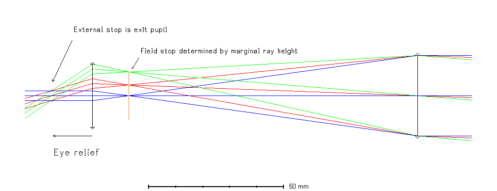
For simplicity, the eyepiece and objective are modeled as paraxial lenses. The design is afocal in object and image space. No image erecting is used. (No prism.)
The implementation consists of:
- Object at infinity with ray angle fields
- Surface 1 just to illustrate inbound rays
- Surface 2 as the fixed stop which defines the exit pupil and eye relief of the non-reversed system
- Surface 3 as a paraxial lens for the eyepiece
- Surface 4 as the field stop. Its position is determine by marginal ray height = 0 solve. It is a real image plane.
- Surface 5 as a paraxial lens for the objective
- The distance to the image plane is unimportant -- just for illustration
For variables:
- The thickness from the field stop to the objective
- The focal lengths of the eyepiece and the objective
The Merit Function Wizard is used to generate operands to minimize angular spot sizes. A few additional operands provide sufficient constraints to determine the design:
- Angular magnification (AMAG) is targeted at -0.125 (1/8x)
- The objective semi-diameter is allowed to float, but a Real Ray Height (REAY) operand targets its semi-diameter at 15mm
Optimization determines the values of the variables. The resulting angular spot radii are zero, which is to be expected with the paraxial lenses. (Too bad we can't buy those.)
Kind regards,
David

Enter your E-mail address. We'll send you an e-mail with instructions to reset your password.
Need more help?
To Chinese users:
Do not provide any information or data that is restricted by applicable law, including by the People’s Republic of China’s Cybersecurity and Data Security Laws ( e.g., Important Data, National Core Data, etc.).
不要提供任何受适用法律,包括中华人民共和国的网络安全和数据安全法限制的信息或数据(如重要数据、国家核心数据等)。