Edge Thickness at full mechanical Semi-Diameter

  • 8 December 2020
  • 3 replies
  • 450 views

Hey there,


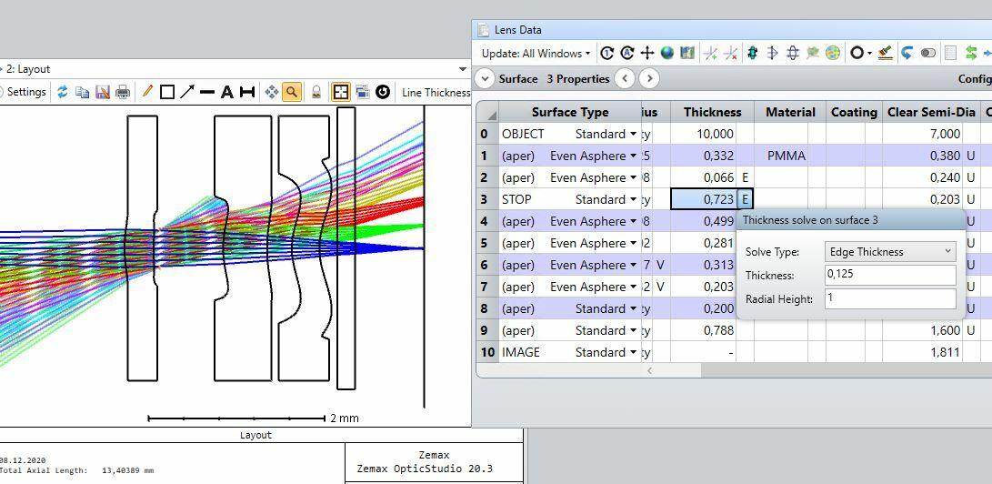
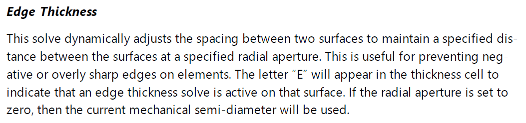
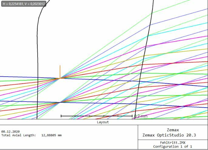
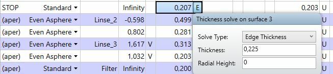
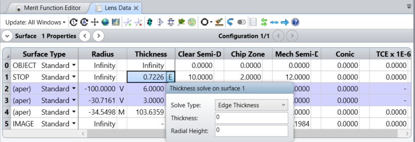
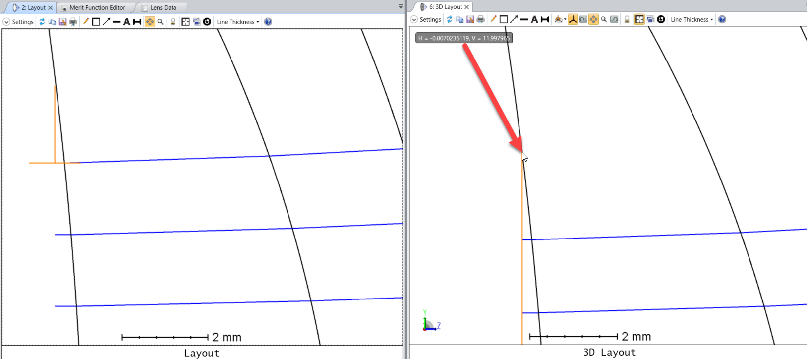
does anyone here know how to achieve a certain edge thickness at the full mechanical semi-diameter having chip zone turned on? Is there any possibility to use e. g. the edge thickness solve function in the lens data editor for the mechanical semi diameter as well? Everytime I try to set the edge thickness to a certain value the following surface removes itself an unpredicted long distance.


Thanks in advance.


Stephan

edgethickness.jpg

3 replies

Userlevel 5
Badge +2

Hello Stephan,


Thanks for your question here!


If you set the radial aperture value in the Edge Thickness solve type to zero, then the current mechanical semi-diameter will be used.


You may find more information about this in the Help file at:


The Setup Tab > Editors Group (Setup Tab) > Lens Data Editor > Solve Types (lens data editor) > Thickness Solves


I tested the Radial aperture parameter and it seems that it uses the current radial coordinates, and not normalized coordinates, I think this is what caused the problem in your case.


You can read more details about the calculation in the Help file at:


Conventions and Definitions > Edge Thickness


I hope this helps, but if you have any further questions, please do not hesitate to contact us!


Best,


Csilla

Hello Csilla,


unfortunately that´s not the case. I´ve tried it and it set the thickness at the height of the clear semi-diameter of the stop surface to that certain value. But what I want is a certain thickness at the mechanical semi-diameter as you already said. Any more ideas?


Best regards,


Stephan

edge_thickness_doesnt_work.jpgedge_thickness_solve.jpg
Userlevel 5
Badge +2

Hi Stephan,


Thanks for getting back to me!

I'm sorry to hear that you have problems with the settings in your file.


As you haven't sent any files, I have checked the settings myself on a sample file, and for that case it worked as expected. Please see the screenshots below and find the file attached:


You can also try to insert the mechanical semi-diameter directly to the Radial Height parameter. It should give the same results.


Isn't it possible that the difference between the clear and the mechanical semi-diameters in your file is so small that you didn't see the difference between them? 


If you cannot make it work on your file, can you please share your file so that we can take a closer look?

If you cannot share the file publicly on the forum, you can open a case with us, so that only you and Zemax engineers will have access to it.


Finally, you can try to use optimization operands instead of the thickness solve to put constraints on the edge thickness. You can use the ETGT - Edge Thickness Greater Than, ETLT - Edge Thickness LessThan, or ETVA - Edge Thickness VAlue operands to form restrictions on one surface. This is discussed in more details in the following forum thread: Edge Thickness Operand · MyZemax


Looking forward to hearing back from you!


Best,


Csilla

Reply