Dear Sir/Madam,
I am trying to use path analysis to analyse rays that reach certain region of my detector (detector colour). So I use filter string to define the interested region. And the path analysis results is shown below. The detector is object 42.
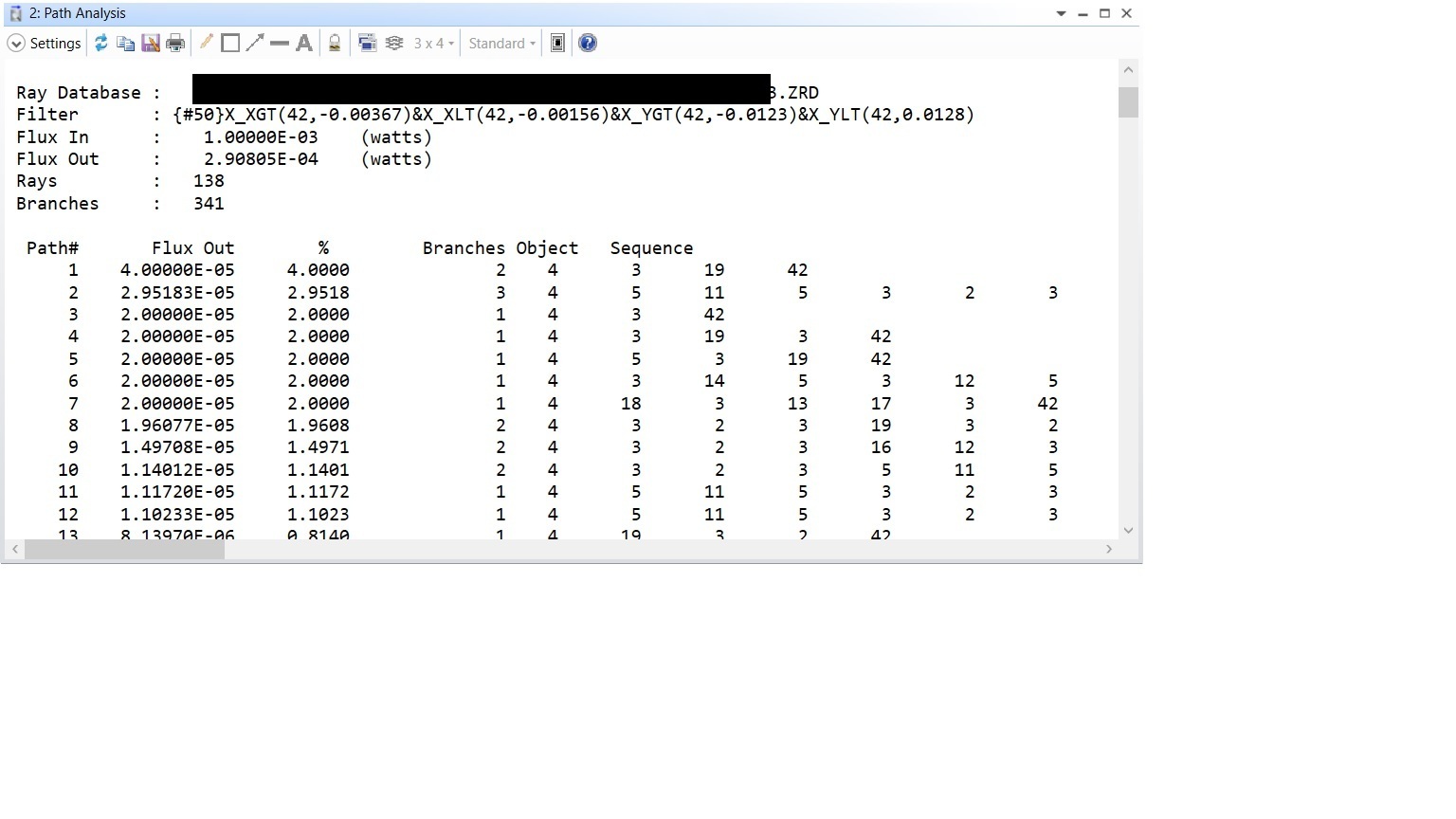
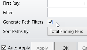
After that, I want to take a look of the first ray path shown in the document above in 3D layout viewer. So I opened the ZRD file in the 3D layout viewer accordingly and use the same filter string with &_1 added at the end. The result is shown below.
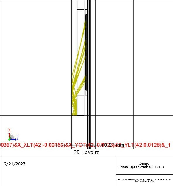
It is surprise to me that in the above picture, there are more than 2 Branches shown. But according to the path analysis result there is supposed to be only 2 branches for the path number 1. So I tried to add&_1 to the end of the string of the path analysis window. The result is shown below:
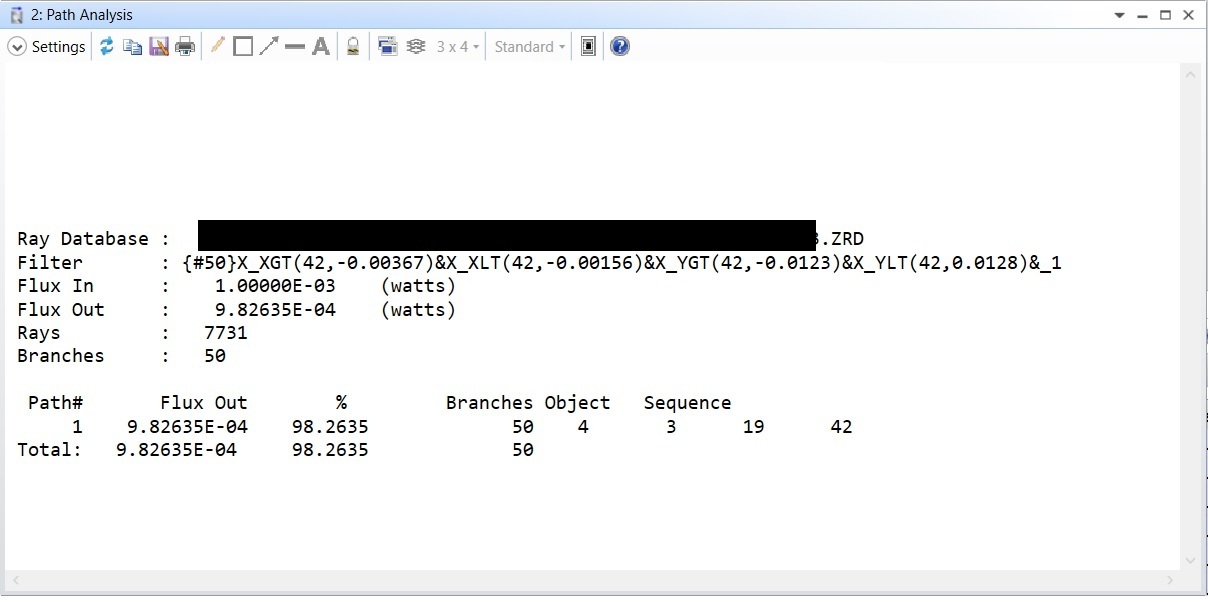
The number of branches changed to 50. May I know the reason of this discrepancy? Did I miss any step in order to see the first path in the path analysis results correctly?
Hope can hear from you soon!
Best Regards,
Jing