Hi all,


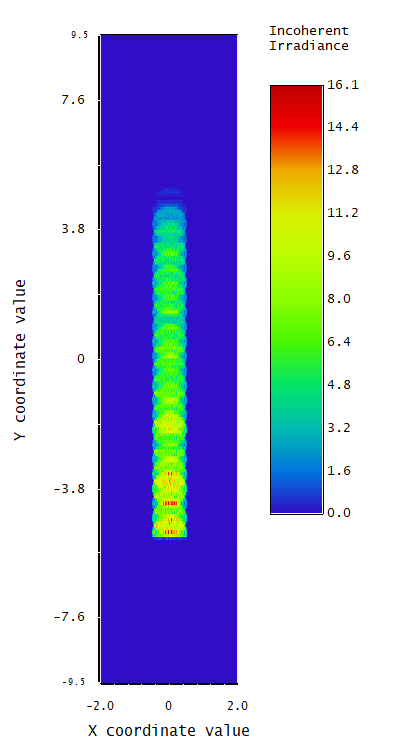
Is there a way to use the data of “detector rectanuglar” as a new source?(see image)
Thanks,

Nadav

Hello Nadav,

Yes. There is a method for saving the rays on any object as a file and then using that file as the data for a Source File object. In the attached example, a Source Ellipse is used to illuminate a Detector Rectangle. A ray trace is run with Save Rays checked and the file name given as “2-Source from Detector.sdf”.  The general form for that is n-filename.sdf, where n designates the number of the object for which rays are saved. Executing the trace puts the sdf file in the proper directory. The saved name does not include the n-.
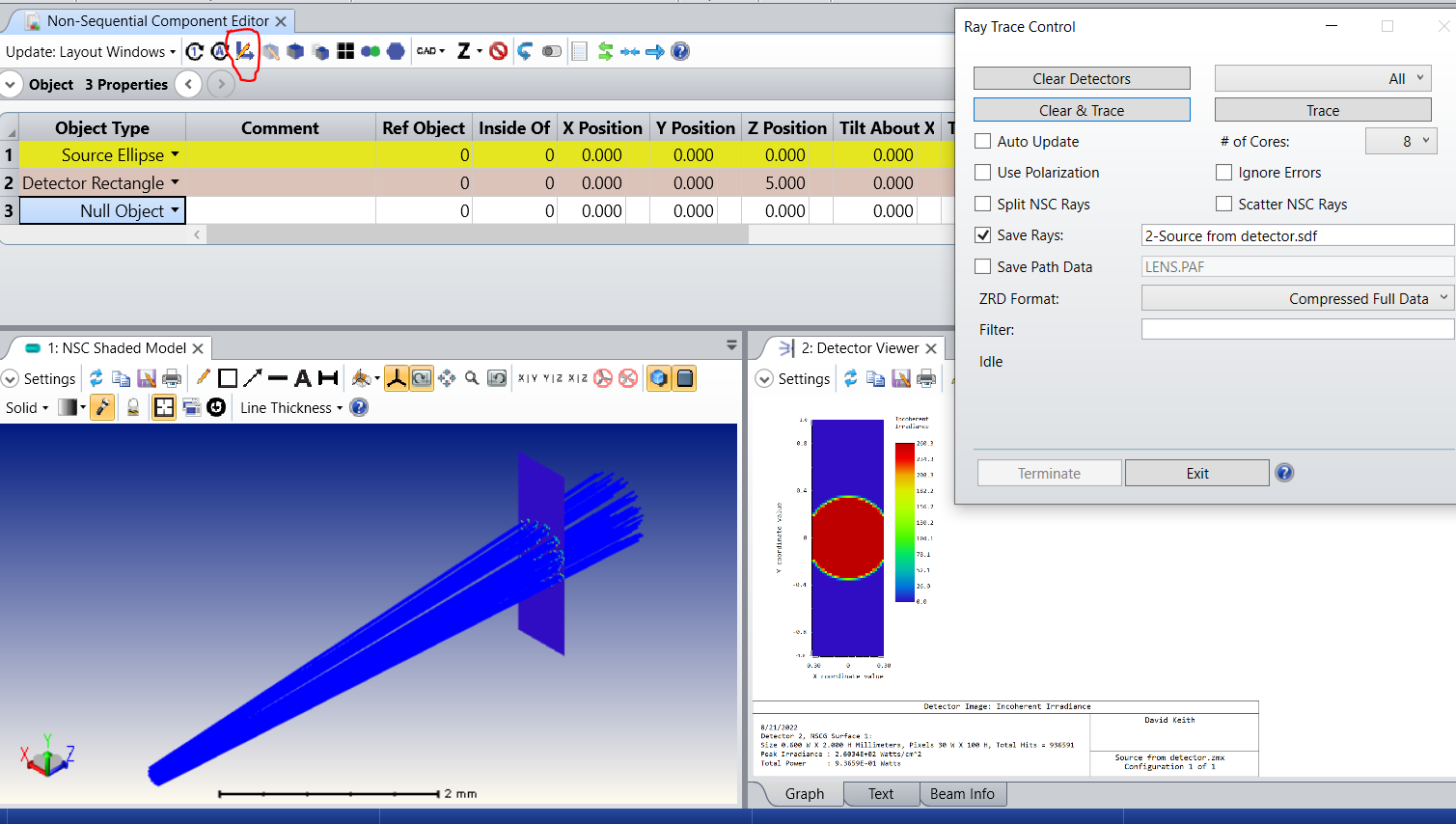


Now that the sdf file has been saved, it can be used as a data file for a Source File object in any non-sequential lens design. In the example, I added a Source File object to the original design and gave it a displacement in Y so we could see the saved rays.
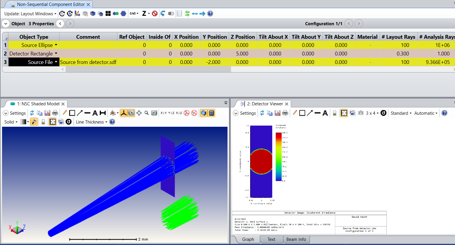
 

Notice that the rays from the Source File are emitted referenced to the same global position as they were saved at in the original trace. If you want the rays to be referenced to the global origin, then you can modify the original file to place the object on which rays are captured at the global origin. This is easily done with the Modify Reference Object tool in the menu bar of the Non-sequential Component Editor.


Hi David,

Thanks for the quick answer. It worked but I have another problem:

I used 1000 rays for the above field, but to get the same field when I export it to “source file” I need ~10e6 rays:

My simulation is complicated and can’t handle it.

Is there any to to solve this?


Thanks again,

Nadav


Hi Nadav,

It is not clear to me what you are saying. 1e6 (in the graphic above) is not a lot of rays.

Do you mean that the trace takes too long to run? If that is the case, perhaps you can live with it. I have often used this technique to produce a ray file where the trace to produce the file took hours or even over night. However, once the file is produced it can be used to continue the work. An example is the illumination path of a projector. A very long trace involving a lot of ray intersections can be used to produce the illumination light body as a ray file, and then that ray file can be used to develop downstream optics.

If you are getting errors regarding the number of ray segments or intersections there is an article on that here.

Sometimes the length of time to produce a trace can be reduced without compromising the results.

It can be that ray splitting or scattering is producing and tracing child rays that carry a negligible amount of power. You can stop OpticStudio from tracing those rays by setting the Minimum Relative or Absolute Ray Intensity to some reasonable value.

It is also possible to reduce the number of rays traced by enabling Simple Ray Splitting. This method does not spilt rays at Fresnel reflections, but rather at each intersection traces either the transmitted or reflected ray with a probability based on the power splitting. This allows us to keep control of the number of traced rays. An article on this is available here.

These controls are found in the Non-sequential table in the System Explorer.


If scattering rather than splitting is generating excess rays, you can also use Importance Sampling and Scatter To controls to improve efficiency. These controls allow us to trace the rays that “matter” by not tracing rays that we decide are unimportant. There is an article about that here.

It is difficult to be specific without knowing more about the design and the exact nature of the problem. You could say more about this or, if it’s not proprietary, include a ZAR file of the design by attaching it, encapsulated in a ZIP folder.


Hi David,


Attached hereby my reply in blue:


It is not clear to me what you are saying. 1e6 (in the graphic above) is not a lot of rays.

Do you mean that the trace takes too long to run? If that is the case, perhaps you can live with it. I have often used this technique to produce a ray file where the trace to produce the file took hours or even over night. However, once the file is produced it can be used to continue the work. An example is the illumination path of a projector. A very long trace involving a lot of ray intersections can be used to produce the illumination light body as a ray file, and then that ray file can be used to develop downstream optics.

The simulation contain a lot of spliting due to beam splitters rays while I am trying to optimize for several parameters and angles. So even 1e4 become lots of rays. Running for hours is too much, and I thought this days are over when I moved from lumerical to zemax :).

If you are getting errors regarding the number of ray segments or intersections there is an article on that here.

Sometimes the length of time to produce a trace can be reduced without compromising the results.

It can be that ray splitting or scattering is producing and tracing child rays that carry a negligible amount of power. You can stop OpticStudio from tracing those rays by setting the Minimum Relative or Absolute Ray Intensity to some reasonable value.

I’ll try again, but it seems that each ray account.

It is also possible to reduce the number of rays traced by enabling Simple Ray Splitting. This method does not spilt rays at Fresnel reflections, but rather at each intersection traces either the transmitted or reflected ray with a probability based on the power splitting. This allows us to keep control of the number of traced rays. An article on this is available here.

Don’t think it will work for us.

These controls are found in the Non-sequential table in the System Explorer.


If scattering rather than splitting is generating excess rays, you can also use Importance Sampling and Scatter To controls to improve efficiency. These controls allow us to trace the rays that “matter” by not tracing rays that we decide are unimportant. There is an article about that here.

Thanks for that.

It is difficult to be specific without knowing more about the design and the exact nature of the problem. You could say more about this or, if it’s not proprietary, include a ZAR file of the design by attaching it, encapsulated in a ZIP folder.

Maybe I will send it in the near future. 

Again, many thanks for the help!


Nadav


Hi Nadav,

There are various options you may be able to use to reduce the number of rays needed for you analysis, but all of them are going to involve some kind of trade-off, and the specific best option will really depend on the specifics of your system and your design criteria. For instance, you can often speed up a complicated run by selecting fewer pixels on the detectors (a very fine mesh really does eat up run time), but at the cost of resolution. David mentioned importance sampling if scattering is an issue for cases where you want to focus on a particular path, but won’t give overall stray light information as easily. There are lots of examples, and I am also unclear on exactly what your needs are.

I do encourage you to open a case with Zemax Support if you are still having issues. We have a non-disclosure policy for any file we receive, and NDAs can be made if need be. We can also do screen shares if you can share a look at the system but not the system files themselves. Please feel free to explore this with us if you continue to have questions.


Hi Kevin,


Thanks for the help. Maybe I’ll open a case in the near future.


Best regards,

Nadav


Reply