Solved

Design stereoscope with two optical paths that offset a constant number with coordinate break

  • December 1, 2022
  • 1 reply
  • 183 views

xiaoleiwang
Forum|alt.badge.img

 Hi all,

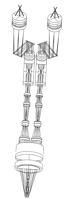
I want use zemax to design stereoscope like the below picture. I got left optical path done, the third doublet offset realized with coordinate break. Now I want add right optical path to the design file, which is identical to the left optical path, just have a offset. How I can use coordinate break to do this? Also, this means it has two image planes. Any suggestion are appreciated.

Thanks,

Xiaolei


Best answer by Ethan

Hi @xiaoleiwang,

Sequential mode requires tracing surfaces in sequence, so achieving the intended multi-path design would be challenging and likely unphysical. You could consider the use of Muti-Configurations as a good approach to quickly move between the left and right optical paths. For more information on the Multi-Configuration Editor and configuration operands, please take a look at this Knowledgebase article:

Using Multi-Configuration Operands to control parameters in a single configuration system – Knowledgebase (zemax.com)

If you do want to trace these paths simultaneously, with two separate detectors, you will need to use Non-Sequential mode for the analysis. OpticStudio provides a convenient tool for converting a Sequential design to Non-Sequential that you can learn more about here:

Converting sequential surfaces to non-sequential objects – Knowledgebase (zemax.com)

Be sure to check the converted design carefully to make sure that everything is represented as you intended.

Best,
Ethan
1 reply

Ethan
En-Lightened
Forum|alt.badge.img+2
  • En-Lightened
  • Answer
  • December 15, 2022

Hi @xiaoleiwang,

Sequential mode requires tracing surfaces in sequence, so achieving the intended multi-path design would be challenging and likely unphysical. You could consider the use of Muti-Configurations as a good approach to quickly move between the left and right optical paths. For more information on the Multi-Configuration Editor and configuration operands, please take a look at this Knowledgebase article:

Using Multi-Configuration Operands to control parameters in a single configuration system – Knowledgebase (zemax.com)

If you do want to trace these paths simultaneously, with two separate detectors, you will need to use Non-Sequential mode for the analysis. OpticStudio provides a convenient tool for converting a Sequential design to Non-Sequential that you can learn more about here:

Converting sequential surfaces to non-sequential objects – Knowledgebase (zemax.com)

Be sure to check the converted design carefully to make sure that everything is represented as you intended.

Best,
Ethan