Solved

Design a camera Lens; Optics Studio

  • 29 August 2023
  • 13 replies
  • 560 views

Badge

Hi everyone,

  1. I wanted to design lens that will be going to infront of a camera with focal length of 8mm.
  1. This lens should see an object of 7x7 mm and transform this object into image on sensor of having size 7.37 x 4.91 mm with pixel values 3072 x 2048
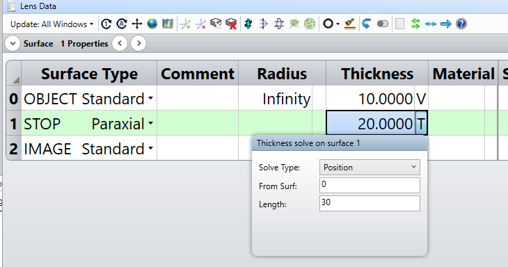
  2. The total track length of the system should be 30 mm.
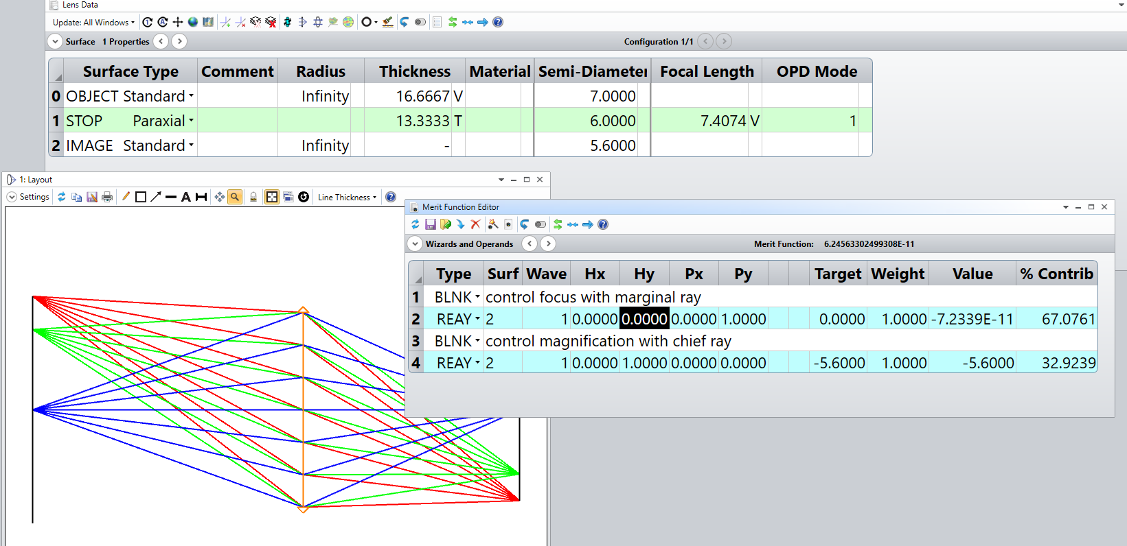
  3. And should have capability to magnify of the object by 0.8 X
  4. Please let me know the design steps of it and its optimization.
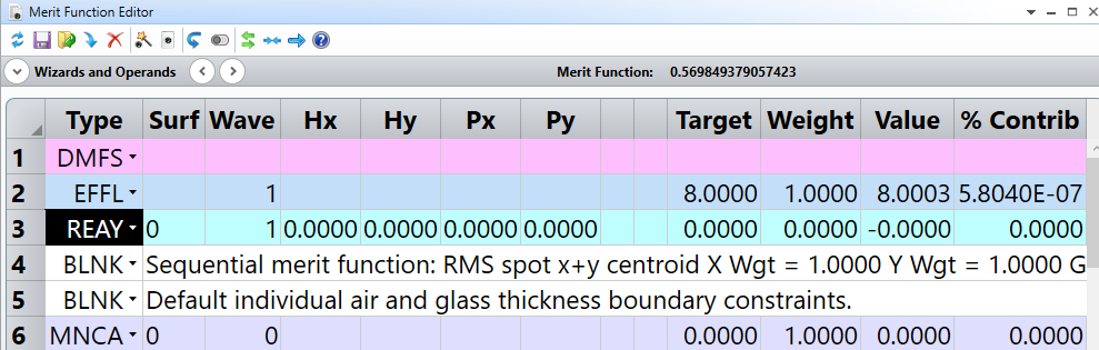
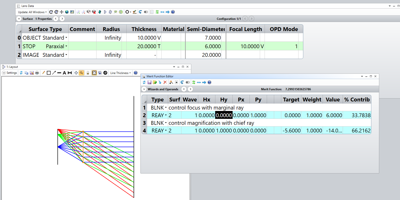
  5. Currently I have done a basic design that has focal length of 8mm.

Please find the attachment of the zemax file.


Thanks

icon

Best answer by Mark.Nicholson 29 August 2023, 18:35

View original

13 replies

Userlevel 7
Badge +3

Hi Ashok,

This video: 

Is useful for that’ where do you start’ kind of question. It sound like you need object height as your field definition, and set the magnification using a REAY operand on the chief ray from the edge of the field to have the desired height. A Thickness solve can be used to constrain the overall system length. I’d optimize for best RMS spot size, unless there is a compelling reason to do otherwise.

  • Mark
Badge

Thank you Nicholson sir,

I’ll go through this video and design it.

But if you have anything with respect to real system and its optimization for the same. Please forward me that as well.

Thanks,

Ashok

Userlevel 7
Badge +3

What you’ve done looks good to me. In your merit function:

I’d move the EFFL and REAY to before the DMFS line so they don’t get overwritten when you rebuild the merit function or use the Optimization Wizard again.

Also your REAY operand isn’t doing anything. I’d make it trace the chief ray (hy= +1) to the image plane and target it to be 0.8 of the object size with a weight of 1.


  • Mark
Userlevel 7
Badge +3

Hi Ashok,

I built a simple starting point design for you, as an example.

You don’t say what the aperture of the lens is to be, so I used 12 mm as this is what you used in your file. I use a position solve on the thickness of the paraxial lens to maintain a total thickness of 30 mm, as per the spec:

The optimization variables are just the distance from the opbject to the lens, and the EFL of the paraxial lens. In the merit function I target the marginal ray to a height of zero on the image surface, and the chief ray to a height of -7*.8 = -5.6. Hitting the optimize button gives:

so you need a lens system with EFL 7.4. I know you said 8mm, but that’s not consistent with the conjugate ratio imposed by the 30 mm total track and the stated magnification. You can define any two of the three, but the other one must be set by the other two.

I would then replace the paraxial lens with two lenses, either side of the stop, and build a defauly merit function using RMS Spot, say 5 rings and 6 arms plus boundary values. Good luck!


  • Mark
Badge

Thank you sir it is very helpful, but I have one doubt sir why did you selected object size 14 mm as i can see it is showing 7mm a semi diameter of the object? And I want to keep object at a distance 14mm as working distance. 
Thanks.


Ashok

Badge

And i did the same thing but its not coming😥.

And more thing why we have used single paraxial lens sir? why not two? yeah you did mention about to replace paraxial lenses with real lenses. So EFL of collective should be 7.4 mm ryt? and both will be opposite to aperture stops?

Badge

Please check this files sir. I have  design using two paraxial lenses and kept the object height 7 mm on both X and Y as a square of 7x7mm gives semi aperture diameter of 3.5 mm. As you suggested optimized for -3.5 . 0.8 = -2.8 and achieved? 

Doubt ?

  1. Can’t we optimized this for close to 8mm focal length?
  2.  Since i have selected X height also in the field, so do we need to keep Hx and Px as well in the operand window?

    I wish to hear you sir soon.

    Thanks Ashok
Userlevel 3

What NA or F/# is needed? The file is using EPD which is ambiguous unless the stop is at the first surface, and the distance to that surface is fixed.

For this system don’t constrain the EFL, let it float. 

Are you going to actually build this system? There are too many steps for someone to describe the design and tolerancing

process here.

I simplified your file, attached.  I assume this will be a rotationally symmetric system. 

Badge

Thanks sir for your times and the design as well.

I have some limitation with respect to the specification those are -

  1. F# = 2.8
  2. EFL = 8 mm
  3. BFL = 9 mm
  4. Magnification = 0.45 - 0.65
  5. EPD close to 12 mm
  6. FOV or object height = 7x7 mm should fall on 7.37 x 4.91 detector.

Thanks …..

If you have anything else please let me know.


Userlevel 3

What is the total distance from object to image? 
BFL usually means distance from lens to image. Is that what you mean?

Why do you specify EFL?  All that’s important is the mag, system length, BFL.  Is there some reason you need a specific EFL? 

Why specify the EPD if you already specify the F/#?  
Are you going to build this system?  There’s not much point in designing with paraxial lenses. 

Userlevel 3

What wavelengths? 

Badge
  1. Yes I’m going to build this system.
  2. Total system length is 40mm and object is kept at 14 mm from first lens.
  3. EFL I have given just FYI and should not increase more than this because I have one physical system having EFL 8mm wan to keep it same.
  1. Yes BFL mean distance from lens to image.
  2. 630 nm.

I’m not very keen in the designing using paraxial lenses more focused on real lenses.


Thanks..

Badge

What you’ve done looks good to me. In your merit function:

I’d move the EFFL and REAY to before the DMFS line so they don’t get overwritten when you rebuild the merit function or use the Optimization Wizard again.

Also your REAY operand isn’t doing anything. I’d make it trace the chief ray (hy= +1) to the image plane and target it to be 0.8 of the object size with a weight of 1.


  • Mark

Best Answer


Reply