Solved

Decenter Image place

  • 5 January 2023
  • 5 replies
  • 164 views

Dear All,

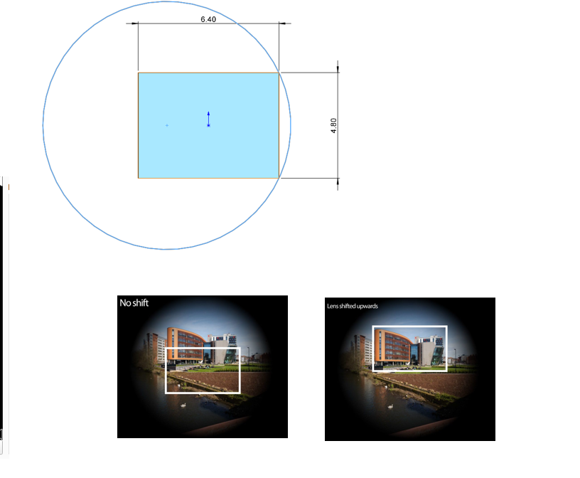
I have a situation here, where I have to shift the lens (image circle) with respect to image sensor/plane, and then visualize the output with image simulation. The image circle should be larger than the imager itself such that no pixels are lost. As an example, the normal vs the shift with larger image circle is shown.


Standard vs larger image circle


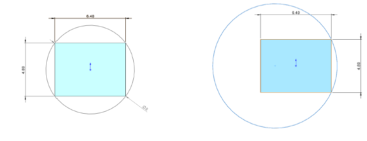
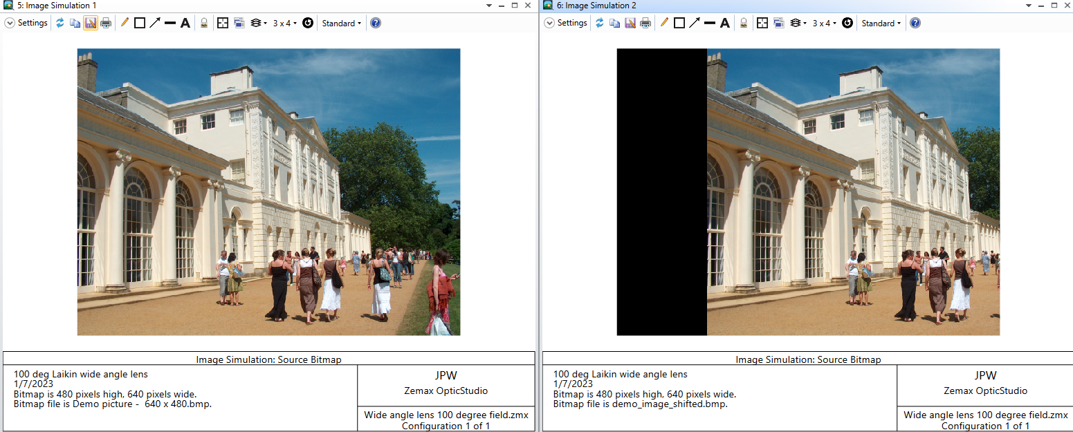
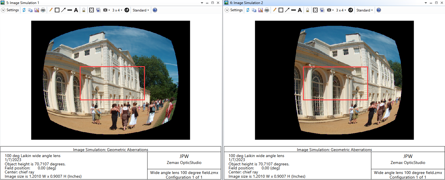
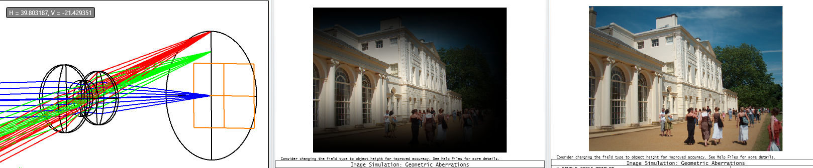
As shown below again, when the lens is shifted a different FOV is captured by the Sensor. This is what I want to simulate and then compare it with the unshifted position. How to achieve that? Simple Decentring the image plane doesn’t work, maybe i did something wrong? Another way could be is to move the lens system together with the field points but it doesn’t work as well, as field points are fixed? Any ideas, how to realize it? Thanks in advance


icon

Best answer by Jeff.Wilde 7 January 2023, 22:54

View original

5 replies

Userlevel 7
Badge +3

@Zain.Ali:

Maybe I don’t fully understand your question, but it seems as though you have already solved the problem.  You show what appears to be a simulated image with a large image circle.  The white boxes show two different regions of interest for two different sensor locations.  For simulation, it shouldn’t matter if you shift the sensor while keeping the lens fixed, or vice versa -- you get the same relative displacement.  Am I missing something?

Regards,

Jeff 

@Jeff.Wilde  Let me clear it a bit more as it is not easy to describe, or may be not intuitive here in simulation as in practice. here is the link to some explanation on what I am trying to achieve: Explaining Shifting the Lens w.r.t Sensor   ( watch till 2:26 minutes)

As an example, the very right side is the default input from Zemax, and this is what the sensor sees. Now in reality the Lens is capable to see to see more as it has bigger image circle, Now principally if I Shift the sensor to the left as an example the right part of the image (FOV) should disappear but correspondingly the left part should appear now. But we should not have any dark corners since the sensor is still inside the image circle. Maybe a different type of input is required? Moving simply the lens doesn’t help as well.


Maybe the video helped to clearify a bit better. 😬


Userlevel 7
Badge +3

I still don’t see the problem.  If you simulate image formation over a large image circle, then you can extract whatever subset of pixels you like corresponding to a particular location of the sensor (with the constraint that the sensor be fully contained within the image circle).  Of course vignetting can reduce the image intensity around the boundary of the image circle, so you might not have a sharply-defined image circle.


Userlevel 7
Badge +3

@Zain.Ali:

I gave a little more thought to your problem, and if your lens has non-negligible aberration and/or vignetting, then there would be a difference between shifting the lens + sensor together versus shifting only the sensor or only the lens.  If you want to keep your sensor centered in the FOV, then one option for simulation would be to simply shift the source image.  For example, I took the demo image that comes with OpticStudio, loaded it into Matlab, shifted it horizontally by 150 pixels (which results in a clipped picture), then saved it to a new bmp file. 


Here is a comparison of the original and shifted image simulations:


This may not be what you have in mind, but thought I would mention it anyway…

Regards,

Jeff

@Jeff.Wilde Thank you for looking into this, As I also kind of assumed a different kind of input might be required to realize it in a better way (a bit more intuitive) which you have showed here. So, let me try this out. 

Thank you

Best Regards 

Zain

Reply