Solved

Creating pair of 90-degree off-axis parabolas (OAPs) with focus between them

  • October 31, 2024
  • 2 replies
  • 243 views

ajs_c

I am trying to create a pair of 90-degree off-axis parabolic mirrors, oriented with the focus between them:

Sketch


As others have suggested, and taking inspiration from this post—Off Axis Parabolic mirror collimation | Zemax Community—I create entire parabolas and then aperture down to only the off-axis sections.


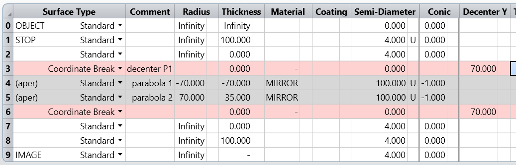
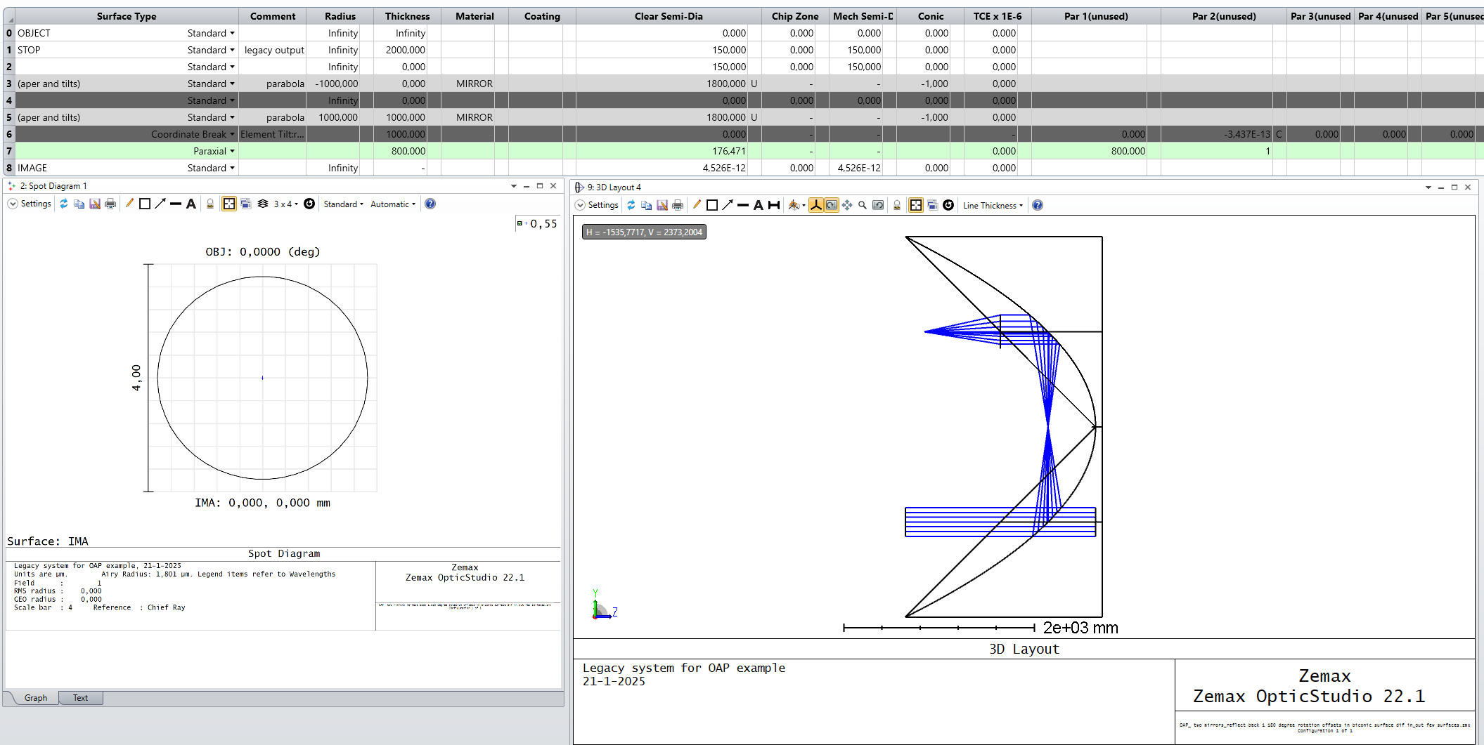
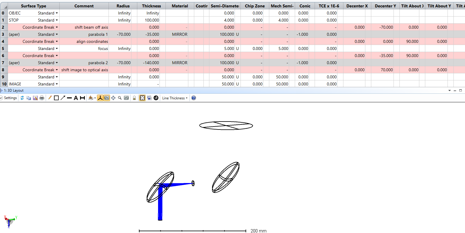
However, I’m struggling to get the correct geometry. This is the layout (with apertures)

Zemax attempt (w/ apertures)

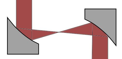
and without the apertures: 

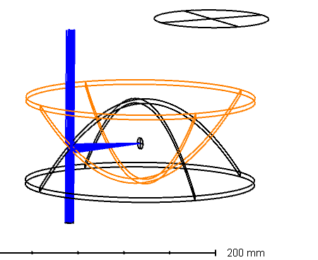
I would like the rays to reach the second parabola and be reflected towards the image. 

Any obvious mistake with the geometry?

Best answer by MichaelH

@ajs_c You’re actually making it way harder than it needs to be.  Since the direction of propagation doesn’t change with each reflection, you don’t need any tilts for your Coordinate Break since the AOI deflects the beam.  You actually only need 2 Coordinate Breaks:

  1. Decenter Mirror 1 (70mm) so the beam hits the off-axis portion of the beam
  2. Decenter the plane after Mirror 2 (70mm) so the rest of the optical system has a new reference

Applying the appropriate apertures, I get the following Lens Data Editor for your system:

After applying a Circular Aperture to the MIRROS surfaces and using the correct Maximum Radio and Aperture Y-Decenter, you’ll get your expected result.

View original
Did this topic help you find an answer to your question?

2 replies

MichaelH
Ansys Staff
Forum|alt.badge.img+2
  • Ansys Staff
  • 342 replies
  • Answer
  • November 1, 2024

@ajs_c You’re actually making it way harder than it needs to be.  Since the direction of propagation doesn’t change with each reflection, you don’t need any tilts for your Coordinate Break since the AOI deflects the beam.  You actually only need 2 Coordinate Breaks:

  1. Decenter Mirror 1 (70mm) so the beam hits the off-axis portion of the beam
  2. Decenter the plane after Mirror 2 (70mm) so the rest of the optical system has a new reference

Applying the appropriate apertures, I get the following Lens Data Editor for your system:

After applying a Circular Aperture to the MIRROS surfaces and using the correct Maximum Radio and Aperture Y-Decenter, you’ll get your expected result.


Gertzemax
  • Single Emitter
  • 1 reply
  • January 21, 2025

Hello,

I also have been struggling a bit with the OAP, and this indeed is a very compact set-up. I did notice in setting up a pair of OAP with some coordinate breaks for retro reflection, that I could get a perfect spot diagram (with a paraxial lens), but I noticed that the final semi-diameter was not idential to the stop semi-diameter. So I'm a bit puzzled how a perfect spot still could give different semi diameters. I think it has to do with ray tracing to parallel surfaces?


Reply


Cookie policy

We use cookies to enhance and personalize your experience. If you accept you agree to our full cookie policy. Learn more about our cookies.

 
Cookie settings