Hi there!
Thanks for posting here on the MyZemax forums.
I've taken a look at your files here, and I think I am generally understanding what you're attempting to accomplish here. It seems like you're hoping to have both of your Grid Phase profiles have a net effect of no impact to the beam. Please let me know if my understanding is incorrect here, though!
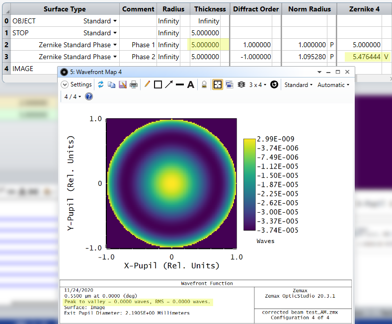
I think the overall issue is that while you are defining roughly the same, but opposite, phase profile on each Grid Phase surface, I think the intermediate propagation is giving you issues in 'preserving' your performance. Another way to observe this is with an input collimated beam, modeled with rays, and using Zernike Standard Phase surfaces rather than Grid Phases (just to keep it simpler):
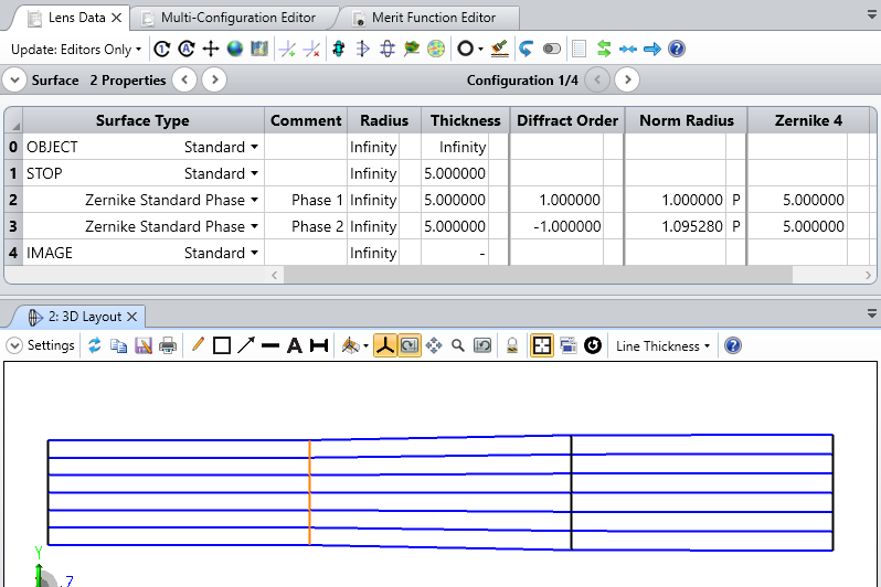
So, in the above screenshot, I have only defined a value for Z4, defocus. They are equal on both Surface 2 and 3, just with opposite sign Diffract Order values. The Normalization Radius is also set so that each surface has the same phase adjustment across the normalized pupil. Even in this case, the resulting Wavefront Map analysis shows that we do not obtain a flat wavefront:
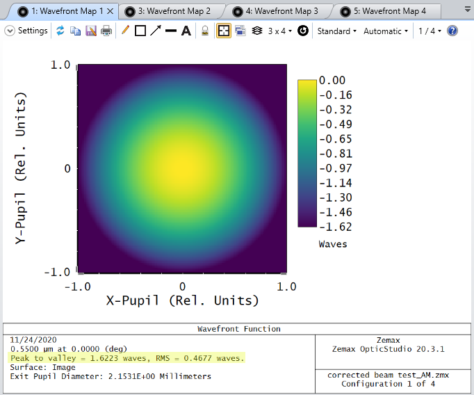
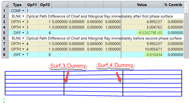
This is because while we defined equal but opposite phase profiles on Surfaces 2 and 3, the intermediate propagation will result in the rays themselves collecting additional OPD in traveling. The marginal rays will be more deviated from the chief ray, meaning the same phase profile on the second phase surface won't entirely undo the effects of the first phase surface. This can also be observed in the Merit Function Editor using OPTH (I temporarily added in dummy surfaces at Surf 3 and 4, between the phase surfaces, so you can see how the optical path accumulates for the chief and marginal ray):
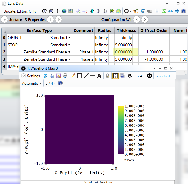
So, really, the ideal location for these two surfaces would be on top of each other, as that would properly undo the imparted phase of the first surface:
Otherwise, you'd essentially need to find a new phase profile for the second phase surface, either through optimization or other means, that would retrieve beam performance:
Please let us know how these thoughts work out for you, or if I've misunderstood any details here!
~ Angel

