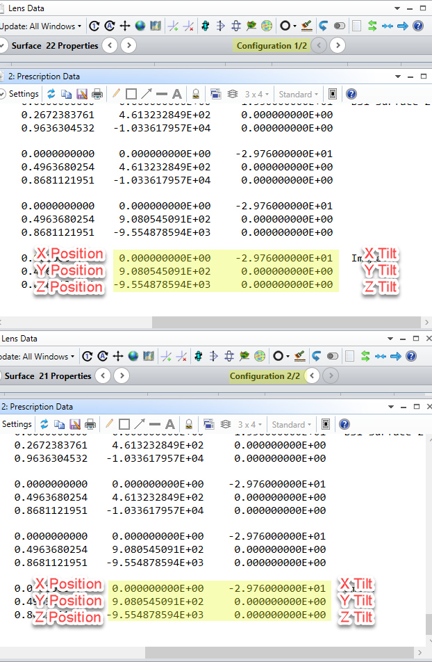
I am trying to insert a two wedge plates and use the multi-configuration to insert a tilt on the optic (similar to a misalignment). If I zoom into the last optic, I see a shift in the optic when comparing the misaligned and the non misaligned systems. 


Configuration 1 is the baseline, configuration 2 simulates misalignment.


the L1a has a -9 tilt with respect to the gut ray. The L1a has a 1.5deg wedge and exits.


the L1a has a 9 tilt with respect to the gut ray. The L1a has a -1.5deg wedge and exits.


I suspect my coordinate returns are wrong. 

updated zemax files


Hi Mary,


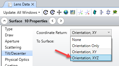
Thanks for your question and sharing your system here. It looks like the issue you're running into is the fact that your Coordinate Return defintion on Surface 10 was set to 'Orientation, XY' rather than 'Orientation, XYZ'. You therefore were not returning to the same orientation and 3D space after Surface 10, resulting in some Z-offset that was adjusting later parts of your system:


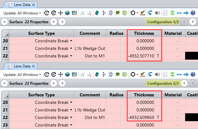
After that, there was still some further devation between configurations due to your Position Solve on Surface 22:


This will result in different placements of your elements after Surface 23. Removing this solve by setting it to 'Fixed' will make both configurations have identical placements for your surfaces, except for the tilted L1a lens:


Let us know if you have any further questions here. Thanks!


~ Angel


The file on this forum is a simplified file but when I applied it to the real file, I still has a translation. I cannot post the file online. Is there a email address I can send to for further assistance?


Mary


Hi Mary


You can open a case on the portal: https://my.zemax.com/en-US/support/cases/create-case/


If you prefer, send an email to support@zemax.com.


Thank you.


Sandrine


Reply