Solved

convert grid sag surface to grid sag lens

  • 10 August 2022
  • 6 replies
  • 268 views

Hi everybody,

I converted the measured surface data into a .Dat format, so i can import it now as grid sag surface in sequential mode.
→ https://support.zemax.com/hc/en-us/articles/1500005490241-How-to-use-the-Grid-Sag-surface-type#importing-a-grid-sag-surface-0-2

Is there any way to compound both surfaces to a volume in Seq. Mode? I tried to use non sequential component and Grid Sag Lens 2 , but .Dat-format is not compatible with this object type.

Regards,
Ata

icon

Best answer by David.Nguyen 11 August 2022, 14:15

View original

6 replies

Userlevel 7
Badge +2

Hi Amarandi,


In sequential mode, grid sag surfaces uses .DAT files. However, non-sequential components, such as Grid Sag Lens 2 require a .GRD file extension. Here’s an excerpt from the Help File about Importing Grid Data:

The file must be in ASCII and end in the extension .DAT (for files used by NSC objects, the extension should be .GRD)


The file can remain the same, just change the extension to .GRD and you should be able to use it with Grid Sag Lens 2.

Hope this helps.

Take care,


David

Hey David,

thank you for your answer.

It did worked very well. One Problem still i am facing is rotating one of two measured surfaces to construct my double convex lens. I used two grid sag lens in non-seq Component and did tilt one of two surfaces about Y-Axis.  But i would like to combine both to a single lens instead. I tried Grid Sag Lens 2 + Rear tilt 180° and the Boolean Native/CAD. Neither of them worked in this case.

I hope i made my point clear :)

thank you in advance.

Ata


Userlevel 7
Badge +2

Hi Amarandi,


I’m a little surprised by the Rear Tilt Z of 180 deg result, but I guess it makes sense. Unless you know how the two surfaces should be connected, it is safer to assume that they should remain connected to their corresponding location without a tilt.

However, I don’t see why it doesn’t work with two Grid Sag Lens in your case. This is what I tried:

  1. I generated a cylindrical grid profile
  2. Created two Grid Sag Lens with this profile
  3. Put a Tilt About X of 180 deg on one Grid Sag Lens
  4. Put a Tilt About Z of 90 deg on the same Grid Sag Lens (I could have applied this tilt to either lens)

This is the result (also attached to my reply, it should contain the grid file):

Let me know if this works for you. Take care,


David

Hey David,

it works if you use Object Type: Grid Lens , but if you use Object Type: Grid Lens 2 and you put a tilt about Y at Rear Surface  it will not work.
Maybe the screenshot can describe it better.

Regards,
Ata


Userlevel 7
Badge +2

Hey Amarandi,


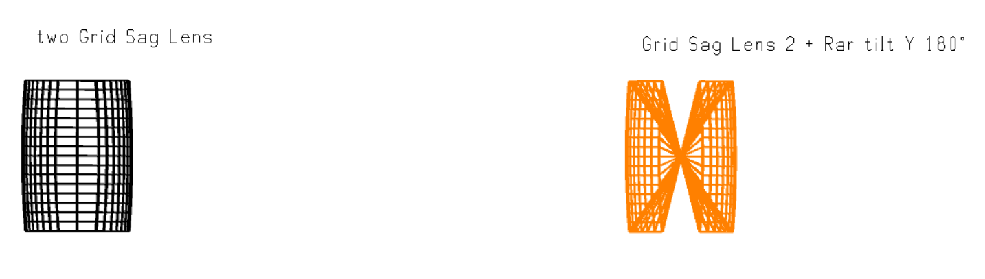
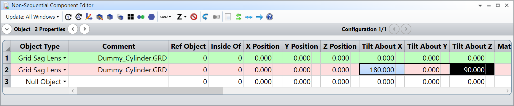
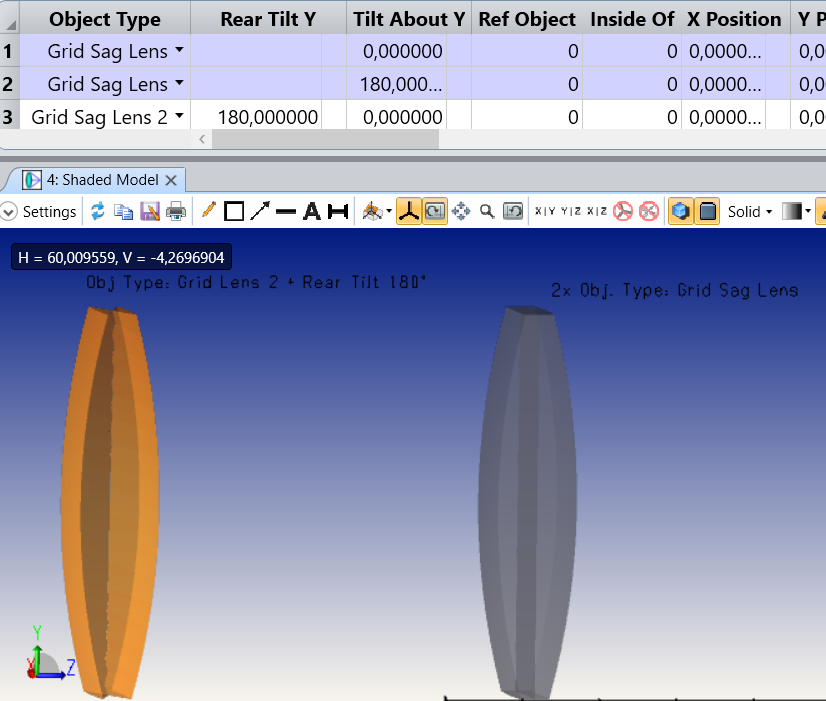
Sorry, I didn’t understand your point before. I arrive to the same conclusion as yourself. It doesn’t work with Grid Sag Lens 2, but as I said, I’m not totally surprised. If you rotate the rear surface, how is OS supposed to know how you want the two surfaces connected? It can only assume that the two grids are connected in the same way as they were without the tilt. That’s why you observe the strange behaviour.

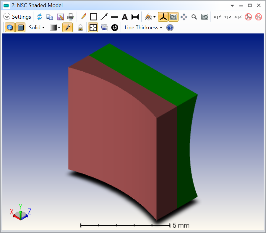
Since it works with two Grid Sag Lens, you should be alright. Are you?

Take care,


David

Hey David,

yes it works with Grid Sag Lens, but i thought there should be an easier way to do the same in one step ;)
thank you very much for your support.

Regards,
Ata

Reply