Solved

Confusion About Fletch Arrow Direction and Paraxial Focal Length in Zemax

  • April 2, 2026
  • 4 replies
  • 59 views

Yang.Yongtao
Fully Spectral
Forum|alt.badge.img

Hi Zemax users,

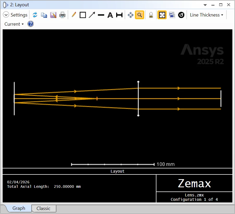
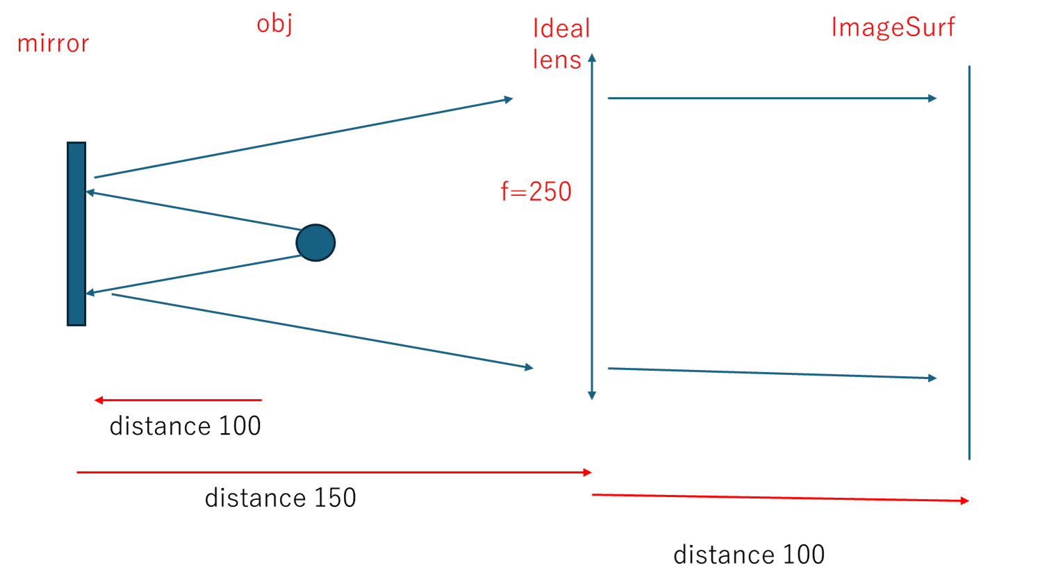
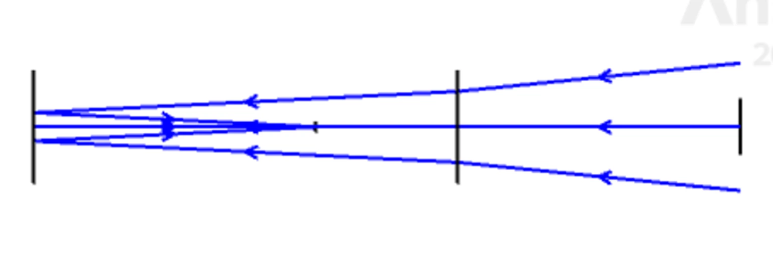
I am trying to set up a lens system layout as shown below, but I am confused about the following points:

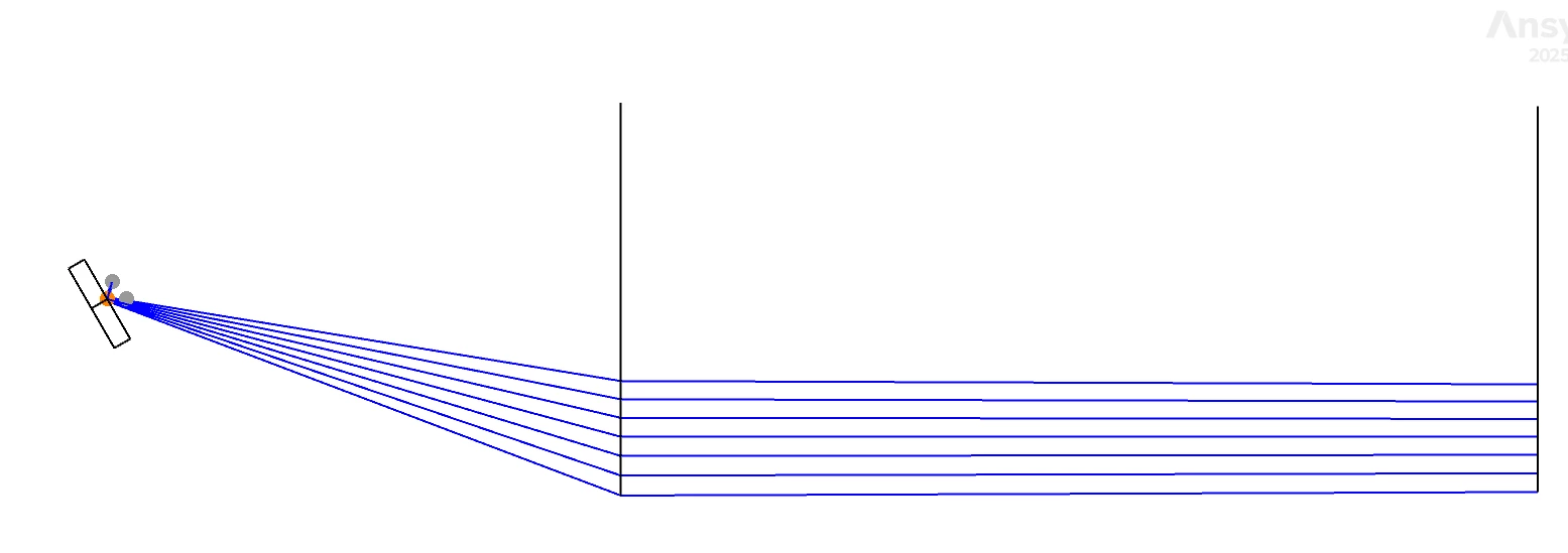
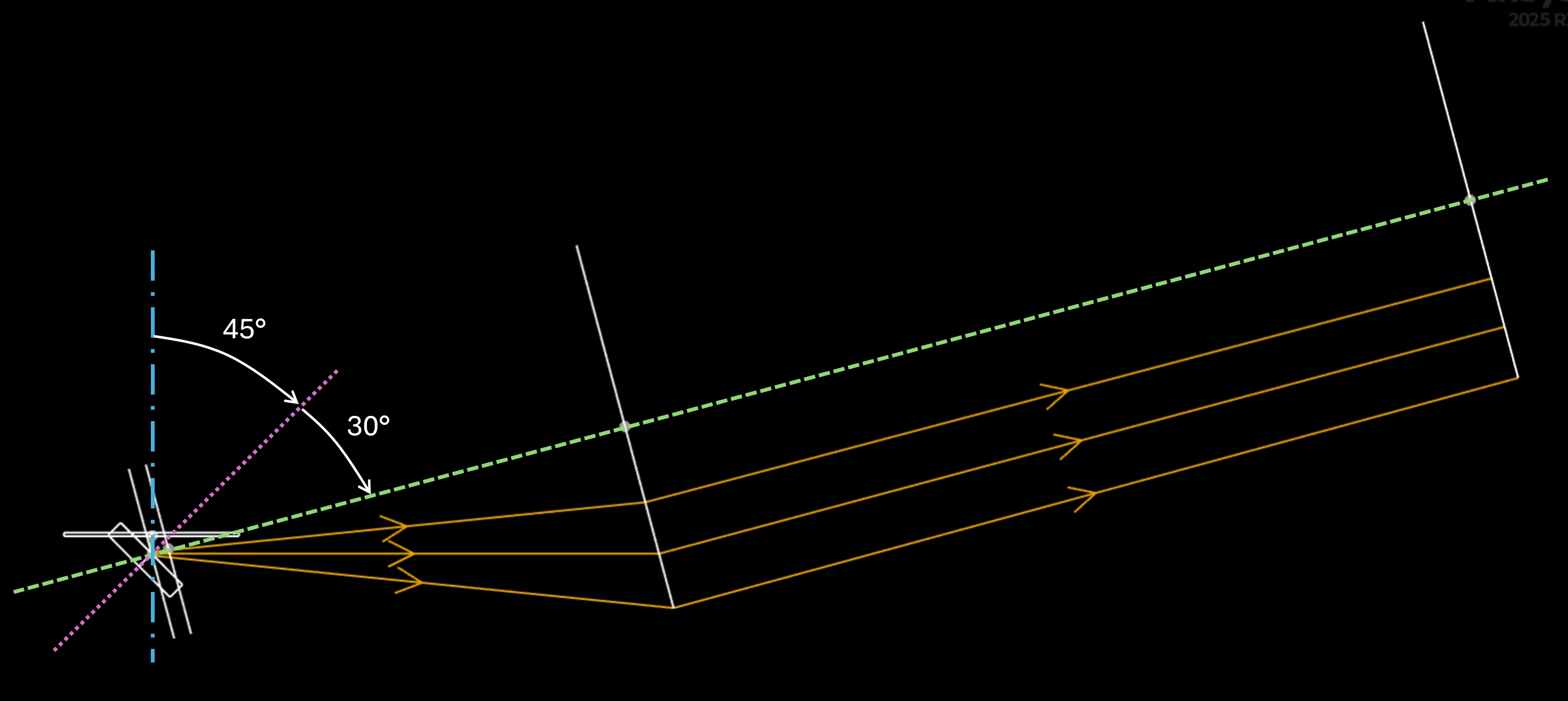
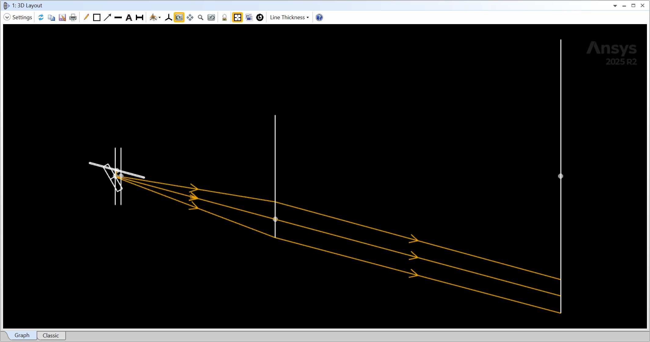
  1. Why does the direction of the Fletch arrows reverse?
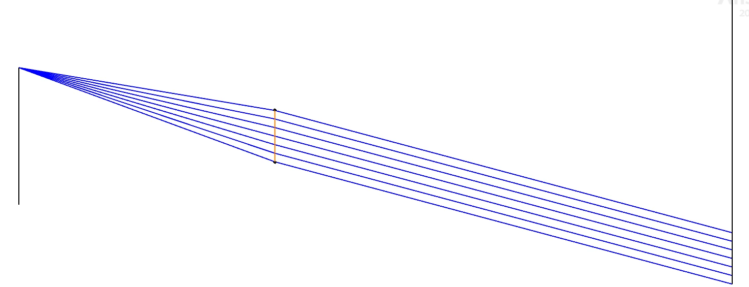
  2. Why does the paraxial focal length of the lens not seem to work as expected?

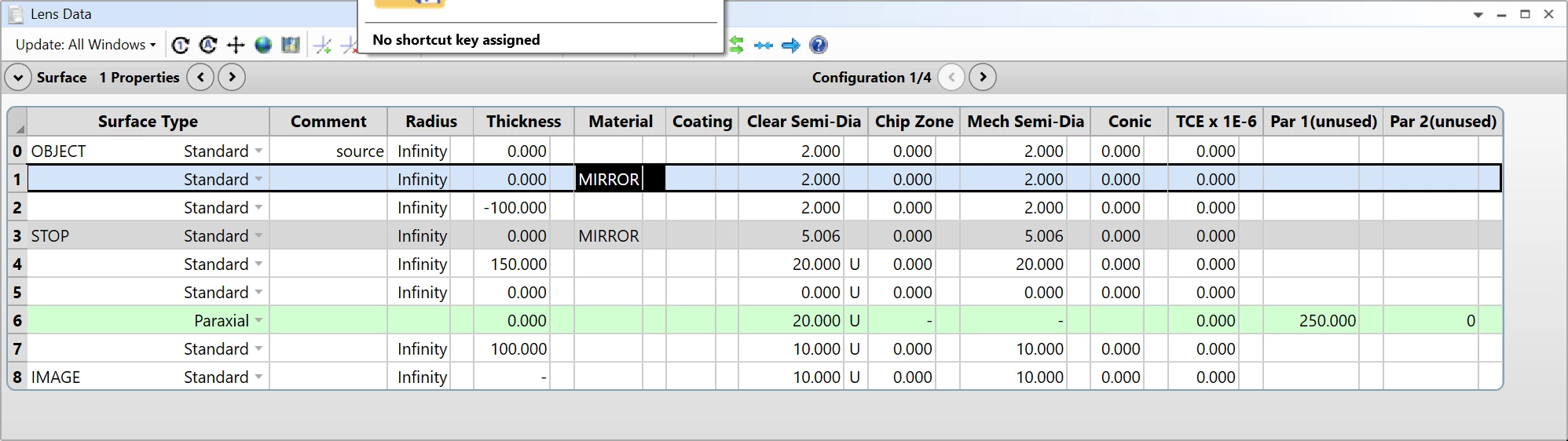
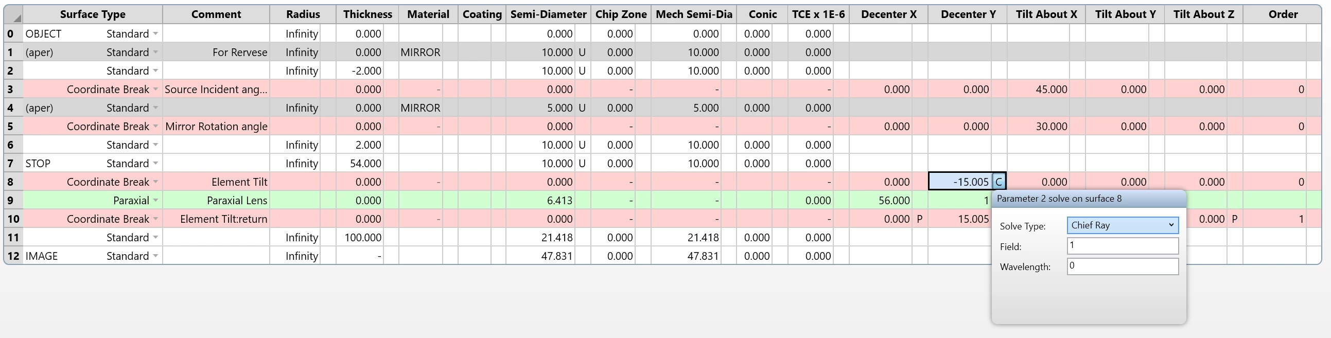
I have attached my data. I would really appreciate any help.

Could you please point out what I am doing wrong?


Expected Layout and Fletch Arrow direction


Attached Zemax Data


Best Regards


Yang

Best answer by David.Nguyen

@Yang.Yongtao 


I’m not totally sure, but I think both issues are related to the fact that you initiate the ray trace in a backward direction by having the first non-zero thickness negative in a “non-mirrored” space.

If you add a surface after the OBJECT and make its Material mirror, then the “positive” propagation direction becomes negative, and the arrows point in the right direction.

This is the same reason the Focal Length wasn’t behaving as expected as well.

In general, I think you want positive thicknesses until the first mirror, then switch to negative thicknesses until the next mirror, and then alternate the signs between mirrors.

I hope this helps.

Take care,


David

4 replies

David.Nguyen
Luminary
Forum|alt.badge.img+2
  • Luminary
  • Answer
  • April 2, 2026

@Yang.Yongtao 


I’m not totally sure, but I think both issues are related to the fact that you initiate the ray trace in a backward direction by having the first non-zero thickness negative in a “non-mirrored” space.

If you add a surface after the OBJECT and make its Material mirror, then the “positive” propagation direction becomes negative, and the arrows point in the right direction.

This is the same reason the Focal Length wasn’t behaving as expected as well.

In general, I think you want positive thicknesses until the first mirror, then switch to negative thicknesses until the next mirror, and then alternate the signs between mirrors.

I hope this helps.

Take care,


David


Yang.Yongtao
Fully Spectral
Forum|alt.badge.img
  • Author
  • Fully Spectral
  • April 2, 2026

@Yang.Yongtao 


I’m not totally sure, but I think both issues are related to the fact that you initiate the ray trace in a backward direction by having the first non-zero thickness negative in a “non-mirrored” space.

If you add a surface after the OBJECT and make its Material mirror, then the “positive” propagation direction becomes negative, and the arrows point in the right direction.

This is the same reason the Focal Length wasn’t behaving as expected as well.

In general, I think you want positive thicknesses until the first mirror, then switch to negative thicknesses until the next mirror, and then alternate the signs between mirrors.

I hope this helps.

Take care,


David

Hi David,

Thanks a lot!

That’s exactly what I wanted to do. I initially thought that using a negative thickness would make the fletch arrow point in the intended direction.

Thanks again for your explanation—not just this time!
“ In general, I think you want positive thicknesses until the first mirror, then switch to negative thicknesses until the next mirror, and then alternate the signs between mirrors.”

Best regards,
Yang


Yang.Yongtao
Fully Spectral
Forum|alt.badge.img
  • Author
  • Fully Spectral
  • April 8, 2026

@Yang.Yongtao 


I’m not totally sure, but I think both issues are related to the fact that you initiate the ray trace in a backward direction by having the first non-zero thickness negative in a “non-mirrored” space.

If you add a surface after the OBJECT and make its Material mirror, then the “positive” propagation direction becomes negative, and the arrows point in the right direction.

This is the same reason the Focal Length wasn’t behaving as expected as well.

In general, I think you want positive thicknesses until the first mirror, then switch to negative thicknesses until the next mirror, and then alternate the signs between mirrors.

I hope this helps.

Take care,


David


@David.Nguyen 


Hi David,

Thanks a lot for your comments, and sorry for bothering you again.

I am trying to set up the layout using a paraxial lens, but I am encountering an issue where the paraxial lens does not behave as expected (see Fig. 1).


Fig1


Fig2


An incident ray entering the paraxial lens at an angle results in parallel rays along the Z‑axis. In a simple layout, I would expect the output rays to still have an angle with respect to the Z‑axis, rather than being perfectly parallel.

I suspect this issue may be related to the coordinate breaks, particularly around Surface 5. It seems that Surface 6 does not fully inherit the coordinate system of Surface 5, and instead still partially follows the coordinate system of Surface 0.

My understanding is that Surface 6 should be a tilted surface parallel to Surface 5, but that does not appear to be the case in my model.

Could you please point out where the settings might be incorrect for the  paraxial lens behaviors and offer some advice on how to fix this?

Best regards,
Yang


David.Nguyen
Luminary
Forum|alt.badge.img+2

@Yang.Yongtao 


This time, I believe the ray tracing behaves as expected and the issue lies in how the Coordinate Breaks (CBs) are setup. I took your 3D Layout, reduced the number of rays to 3, made the first mirror the Global Coordinate Reference and put a X Rotation of -90 degrees in the 3D Layout setting. I then overlaid three axes: the blue dash-dot-dash axis is the original optical axis of the system. With the first coordinate break, you tilt it by +45 degrees and it becomes the dotted pink axis. After the mirror, you tilt it again by an additional +30 degrees (dashed green axis).

Therefore, it makes sense that the rays are parallel to the optical axis after the Paraxial surface. As you can see the rays are all starting on the optical axis (one focal distance away), and so they come out of the Paraxial surface parallel to the optical axis.

I am not sure what is the intended behavior of the system, perhaps you could clarify how the different elements should be positioned with respect to one another.

One possibility is to center the Paraxial surface on the chief ray using a solve. For that, I added a Tilt/Decenter to the Paraxial surface:

The result is as follows:

I am attaching this modified file to my reply. But then again, I’m not really sure if that’s what you want.

Hopefully that answers some of your questions.

Take care,


David