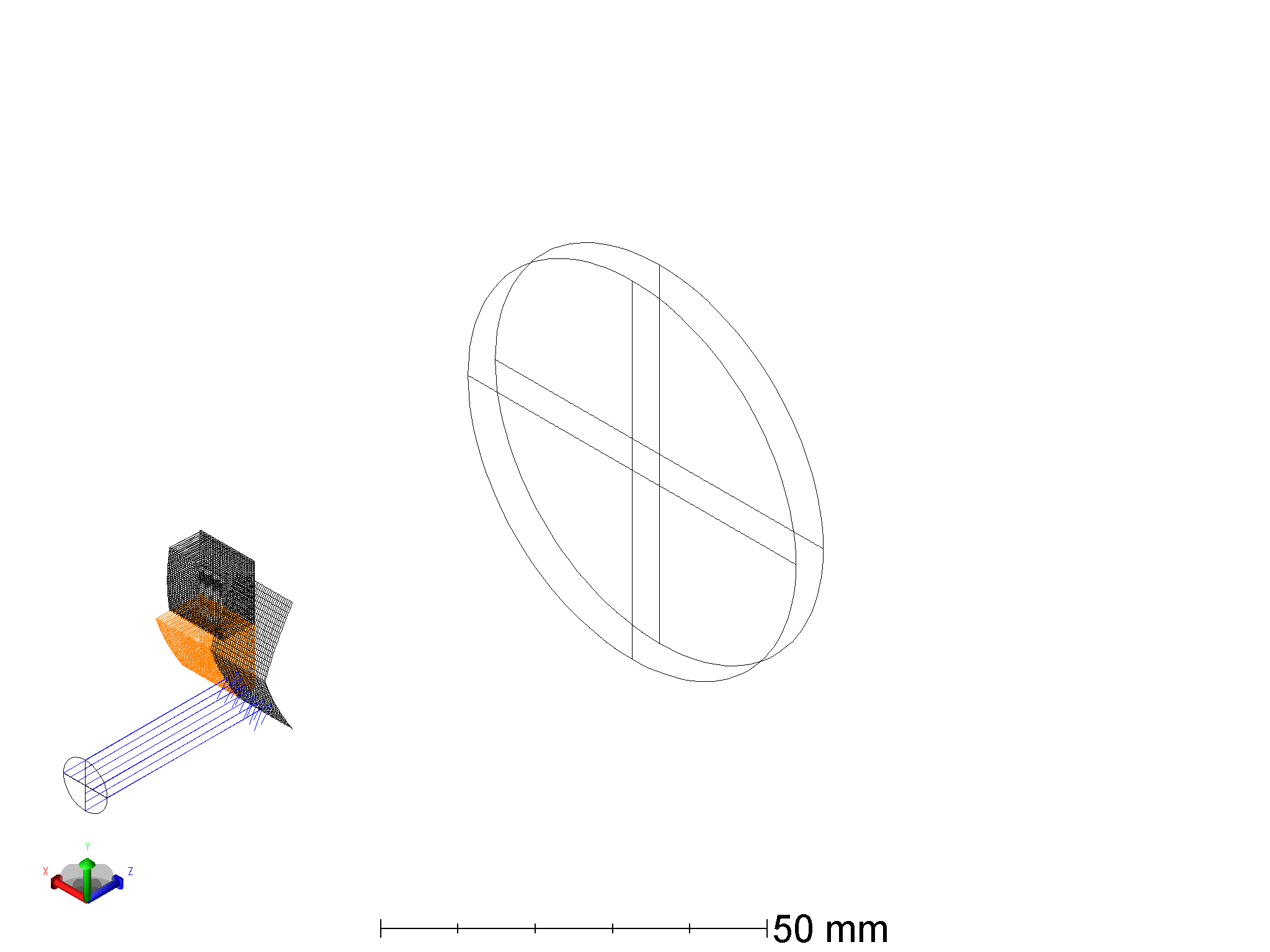
I want to use compound lenses. So I first started with a simple setup to see how this is working at all.
The compound lenses have a flat back and a “toroidal surface odd asphere” as front. A tilted spherical toroidal would do je job, but I did not find an easy way to do that so I use the ^1-coefficient to add wedge.
Two problems.
Both compound lenses do not trace any ray through the system. Only Error rays are produced
The wedge of surf 2 is removed when used for lens 2 (surf 1 and lens 1 don’t show that)
Obviously something is seriously wrong. A made an example file with five configurations. Configs 1-4 put a beam onto the surfaces and lenses subsequently. Config 5 moving making a clear path for the beams.
Can anyone give a hint what I am doing wrong?
Page 1 / 1
Hello Axel,
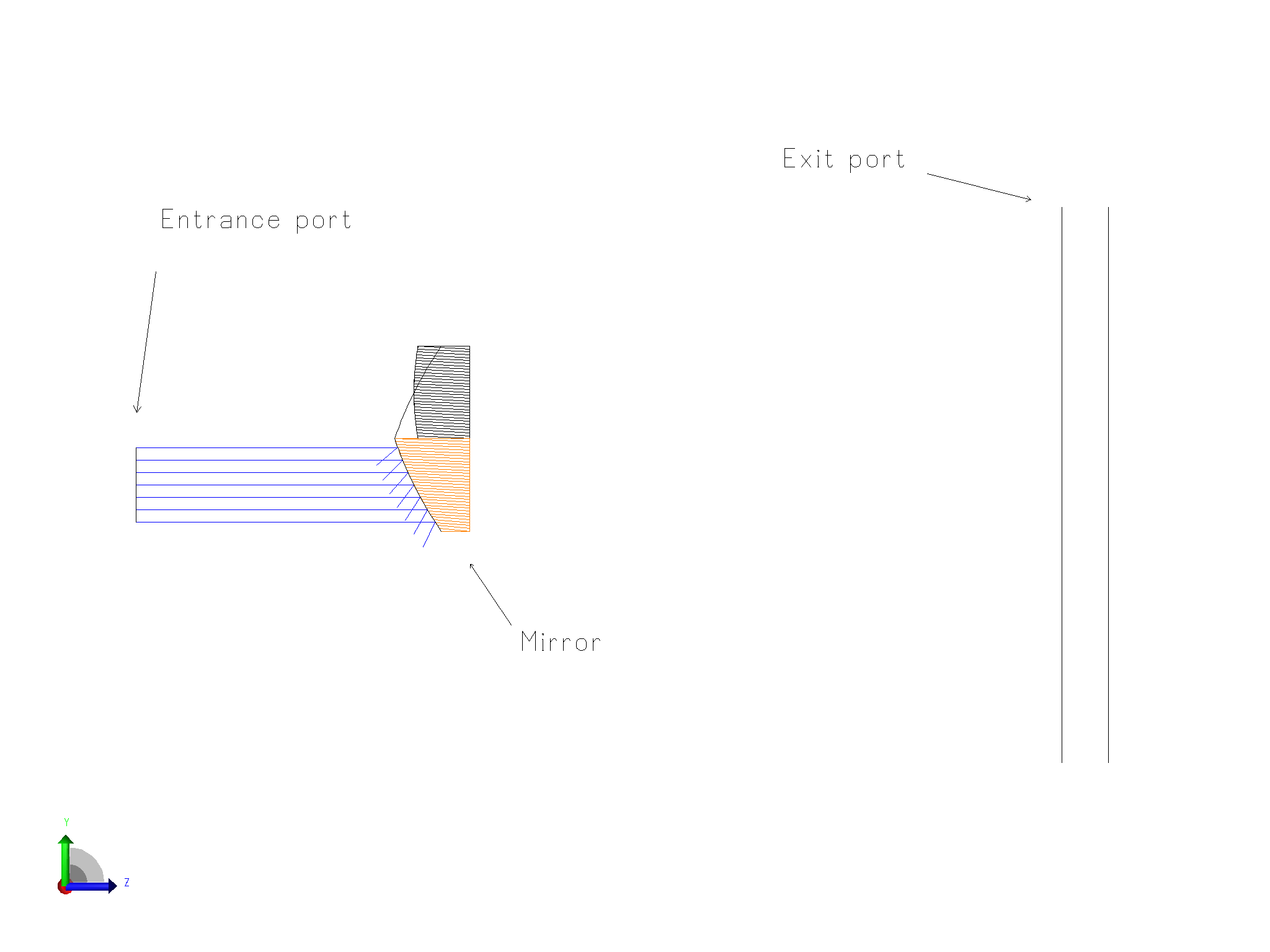
I think you need to look at the non-sequential construction. I don’t think it’s what you intended. I illustrate configuration 1 below. The rays enter through the entrance port and strike a surface designated mirror. They are reflected away from the exit port and strike nothing else.
Hello David,
Thank you for the reply. The file has five configurations. Of which only configs 2 and 4 use the lenses. The example is to show the problem and does not represent the full optical design I am aiming for. I intend to use a compound lens in that, but removed as much as possible to simplify the example.
The surface-objects are from material “mirror” because this seemed to be a valid choice for the surface to do anything tracing-wise. The surfaces are hit in configurations 1 and 3 respectively. In these configurations there is no chance for the rays to hit the nsc-components exit-port.
But that is not the problem.
Problem 1 is, that the lenses are not traceable. They only produces trace errors but no regular hits.
Problem 2 is that surface 1 (NSC-surface-object #3, hit in conf 1) is used as the surface for lens 1 (NSC-volume-object #4, hit in conf 2). Both surfaces line up mostly parallel in your screenshot (lower left and right). But surface 2 (NSC-surface-object #6, hit in config 3) is not used as the surface of lens 2 (NSC-volume-object #7, hit in config 4). Or it is used but the tilt (coeff on y) is removed. The surface of lens 2 is mostly perpendicular to the z-axis in your screenshot, while surface 2 has a significant slant angle.
What I want to achieve as a first step is to have lenses whith a tilted toroidal surface on one side and a plano surface on the other side. It is anticipated that adding a wedge is not mathematically the same as tilting. If there is simpler solution than a compound lens, hints are welcome. Anyway, I would like to know what is wrong with the compound lens.
The same thing happens, when I paste this into a pure NSC-model.
kind regards,
Axel
Hi Axel,
Looking at your NSC Editor I think you are not using the Compound Lens correctly. The Compound Lens needs to specify two surfaces, one for the front and one for the back. These must appear earlier in the editor. You appear to be specifying two compound lenses. But for each of them there is a valid surface specified for the front face, but for the back face of each you specify the Back Surface # as 0. That does not specify a valid surface.
I am having trouble understanding what you are trying to do. But if you are trying to make a single compound lens, with toroidal surfaces for the front an back face, then you should precede the Compound Lens with two surfaces. Each of these should be designed to form the appropriate face. Then specify their line numbers in the Front Surface # and Back Surface # columns of the compound lens.
The two surfaces act only as references in the Compound Lens. They do not need material specifications. Once you see that you have what you want, you can set their properties to Do Not Draw and Rays Ignore. The material and coating specifications for the Compound Lens are specified on it, and not on the referenced surfaces.
I attach a simple example in which the two faces are simple aspheres. I left the surfaces drawn and spaced them away from the lens they define for illustration
If you tell me exactly what sort of lens you are trying to create -- is it one or two, etc -- I might be of more help.
Hello,
Sorry for the confusion about the material of the surface-object and the whole idea behind the design.
I have to transfer the problem to something not revealing any “intellectual property”. Otherwise I would spend weeks of internal discussion.
The objects to model are the compound lenses. If these are traceable without geometry errors I am happy. The surface beeing reflective has no meaning design-wise. Material mirror is just a “debugging-pseudo-assignment” to understand up to which point the NSC-object act as intended and where in the logical chain things start to go wrong.
The problem presented in the examples are the geometry errors. I just want to understand at which parameters a compound lens is valid and when it does produce geometry errors.
Starting from your working example I played a little around.
I still have problems to comprehend what is a valid compound lens, and what is an invalid compound lens just producing geometry errors. I have the suspicion something is wrong inside zemax.
Attached is working and a non-working version of the file. The difference is just that the y-half-width of the toroidal surface is picked from the x-half width. Changing this from pickup to fixed (without changing the resulting value) makes the whole thing traceable without gemoetry errors?? Maybe a few CRTL-A neccessary to see what happens.
Kind regards, Axel
Hi Axel,
The pickup is not the problem. The working file puts rays through the upper lens, which works. The non-working file puts rays through the lower lens. The ray error occurs on the first surface in the NSC group. The displayed rays appear to ignore the lower lens. I suggest sending this in to support.
Hi all,
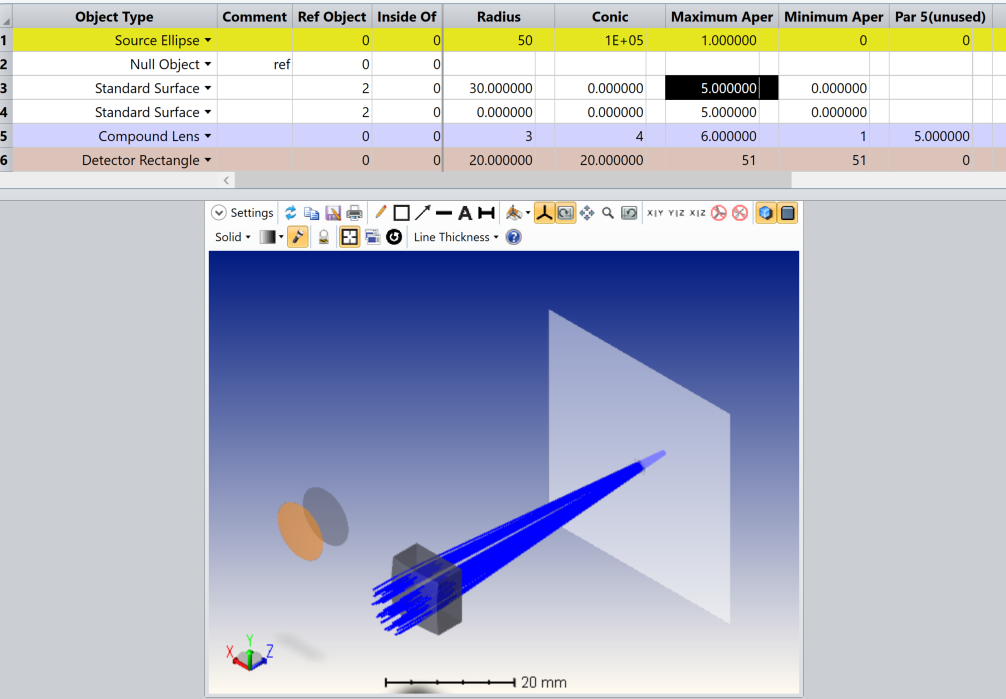
I just wanted to chime in quickly here as we took a look at this file, and I think this is shaping up to be some kind of bug with the Compound Lens object. I’ve isolated it to what seems like a conflict when a parent surface object has some Pickup solve defined on anything defining an aperture (i.e., X/Y Half-Width, Min/Max Aperture, etc.). In fact, I was able to reproduce the issue using a pair of Standard Surfaces with the Compound Lens. Below, we can see a Compound Lens being formed with two Standard Surfaces:
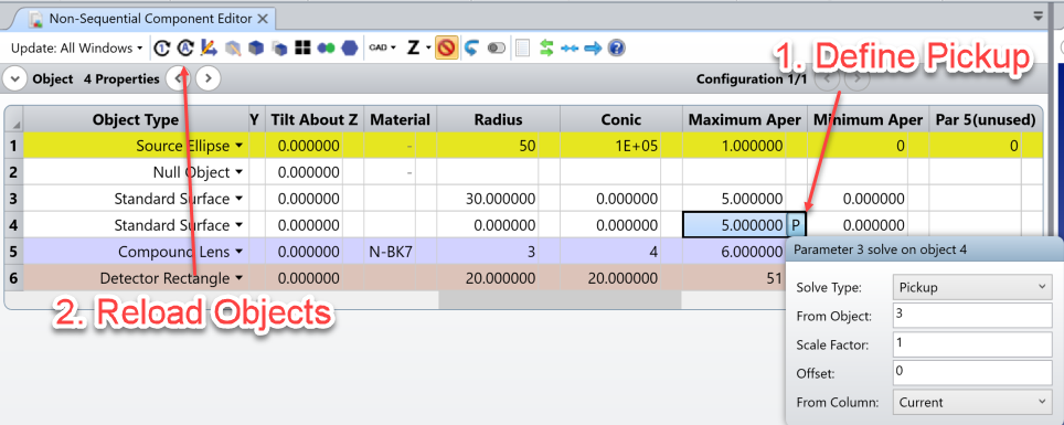
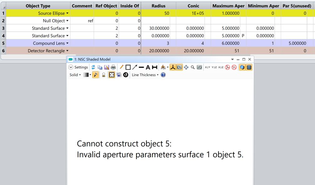
The issue pops up when I attempt to put a Pickup solve on Object 4 so that the Max Aperture can pull the Max Aperture from Object 3 to match, then rebuild the Compound Lens with “Reload All Objects”:
Here, we get an issue where the object is not being built at all, whereas it seems with the Toroidal Odd Asphere, it builds but is behaving erratically in the ray trace. So, at this time, I would recommend not using Pickup solves on those parameters until our Development Team can investigate further.
Thanks all, and let us know if you have any more questions here.