I got a glass sheet with front surface coated with AR coating and backside coated with colored ink, I know the reflectance spectra of the ink as well as AR coating design, the difficulty is that the ink will scatter light, how could I use Zemax to calculate the color measured from front surface of glass? Appreciate your help.
Cheers,
Page 1 / 1
Hi Larry,
Thanks for posting on our forums!
With respect to modeling the output of light through your coating/glass/ink layers, one main detail you’ll need to have in OpticStudio is defining that scatter profile from the ink. In OpticStudio, you’ll need to have some prior information or a way to characterize the scattering behavior of that ink, whether it is a surface scattering definition (i.e., ABg scattering or loading in some BSDF profile) or some bulk scattering definition (i.e., Rayleigh or Mie scattering). We have information on various supported scatter profiles at this article here: What scattering models are available in OpticStudio? – Knowledgebase (zemax.com)
If you have something like that already, then I think you should be able to have a pretty good simulation by creating an object modeling your glass window, coat it appropriately on the front face with your AR definition, and have the correct scatter profile defined on the back of the glass window. If you don’t have information on the scatter properties, and that is something you’re trying to generate (i.e., you have some microscopic particles that you know will do some light scattering and that is what you’re trying to understand), then OpticStudio won’t really be able to provide those results for you. Scattering is best simulated with those profiles/parameterized definitions loaded in.
That said, it does remind me of some general interoperability shared in Ansys products, such as with Lumerical and SPEOS. We have an on-demand webinar that speaks to modeling some nanoscale structures of a display and bringing that information into a macroscale simulation. It’s more related to display technology such as OLED/LED outputs, but I’ll share it here in case you are interested in checking it out: Design Better Displays with Ansys Lumerical and Ansys SPEOS | Webinar
If something like the above functionality interests you, I am sure we could put you in touch with the right folks to speak more specifically to your use case with your ink layer.
Thanks!
Hey Angel,appreciate your professional advice!
I am sorry that I may have dummy questions as I am just a beginner on Zemax,
As the ink is made of pigment particles mixed in the binder, its surface is also smooth on glass, it should be bulk scattering, but I prefer to use surface scattering model like ABg, is this ok?
What’s the right way to characterize ink? Measure Refractive index n and k does not sound right as ink gave scattering reflection instead of specular reflection, collecting ink reflectance spectra at various angles seems to be right approach, for inks with different colors, like red, green, blue ink, how could we take account of the color difference and collect its reflectance spectra at various angles and input in Zemax to calculate the color for the full PVD/ink stack ? Should we collect reflectance spectra of ink through glass or on ink directly? What’s the right spectrophotometer?
Should I use non sequential for the simulation? The stack is simple, Optical stack plus ink on glass, if we measure the color by simply attaching the part on spectrophotometer with integrating sphere using SCI mode and F2 light, how to set up this with Zemax non sequential mode?
Cheers
Larry
Hi Larry,
No worries! We’re happy to help with any questions you might have on using OpticStudio. To get to your particular items:
To be honest, I am not very sure about the loss of information if you change a bulk scattering definition into one approximated by some surface scattering model. That said, if you had some information to work with, such as measured scattering data, we do have this article which might be relevant for your needs:
In OpticStudio, there are a few methods to account for characteristics like color-dependent reflectance based on angles of incidence/wavelengths used to be traced. This sounds like it should be defined as a coating in OpticStudio, as we have various methods to construct coatings, including a TABLE definition which essentially just takes in a dataset of incident angles, incoming wavelength, and reflection/transmission coefficients. However, this would just model specular behavior, and I know you mentioned that there should be scattering reflection.
You might be able to pair up complementary specular coatings (define how much power should be retained for certain wavelengths) and then have an associated scattering profile to then send the rays in the correct scattering distribution. As for defining these in OpticStudio, I would point you to the following resources (which also cover coating definitions on objects):
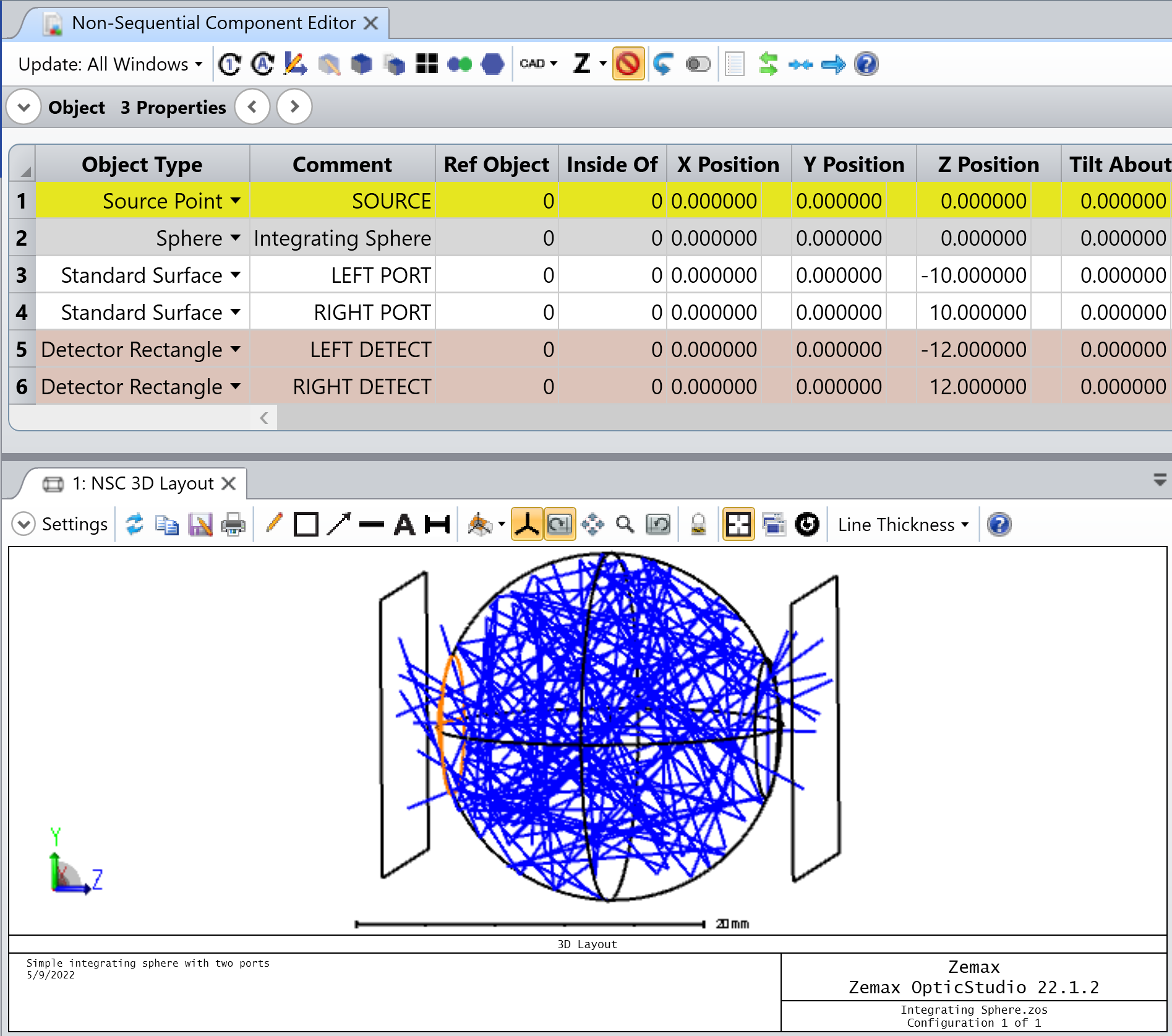
For this kind of system, I would definitely recommend Non-Sequential Mode. Non-Sequential Mode will allow you to define sources, geometry, and detectors, and place them arbitrarily in 3D space. It’s best equipped to handle situations with wide scattering, modeling illumination systems, and so on. Actually, in all OpticStudio installs, we do have a sample file of an integrating sphere, which is located by default at C:\...\Zemax\Samples\Non-sequential\Miscellaneous\Integrating Sphere.zos
This might be a good starting point -- from here, you can alter the source geometry to be representative of your input distribution and begin adding in Rectangular Volume objects with the coating/scattering definitions based on your needs as discussed above. I would also highly encourage you to take a look at our free tutorial on illumination systems, which I think nicely covers a lot of Non-Sequential Mode topics.
Hey Angel,
Thanks for you valuable advice!
“You might be able to pair up complementary specular coatings (define how much power should be retained for certain wavelengths) and then have an associated scattering profile to then send the rays in the correct scattering distribution.”
I used KONICA MINOLTA spectrophotometer CM-3700A to collect reflectance spectra and color of the ink, it is not specular reflectance spectra, instead it use integrating sphere to collect scattering reflectance from all angle, the light source is also scattering light, can I use this scattering reflectance data to combine with Zemax built-in scattering model to simulate the color of PVD/ink combined stack? By doing this way, we basically assume that there is no color-dependent reflectance based on angles of incidence, right? Can Zemax built-in scattering model handle color-dependent reflectance based on angles of incidence?
Another question: When simulating specular reflection, we do simulation on s and p polarization separately and then combine them to calculate reflectance, this approach can not be applied to scattering reflectance, right?