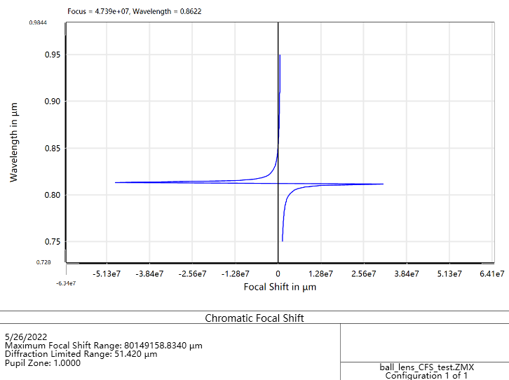
I just found a problem related with chromatic focal shift in my ball lens design. When the pupil zone is set to 0, it is a very small number, while it can be extremely large when the pupil zone is set to 1. Is there something wrong with it ? Which value should I trust?
I tested it on Zemax 2017 and 2019, but I lost my license recently, so I can not test on the lateset version.
I also attach the zmx file for your testing.
Thank you
Oliver
Best answer by Jeff.Wilde
Hi Oliver,
There are a few important issues in your model that need correction:
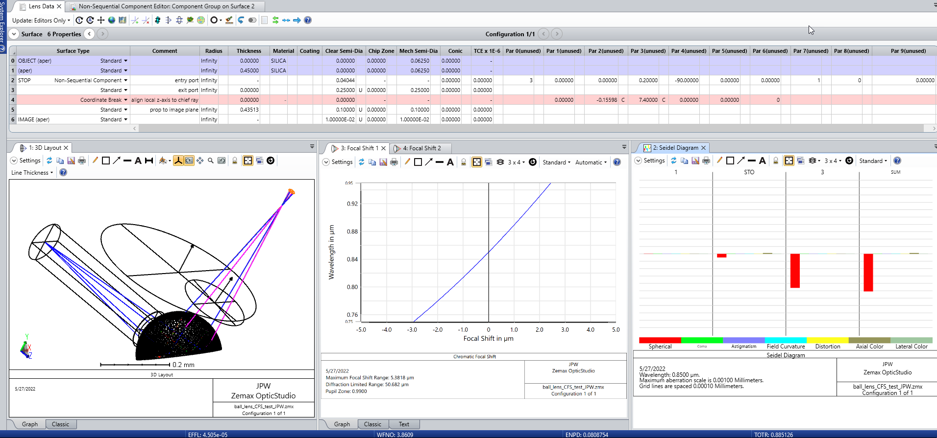
1. The stop surface (and hence, in this case, the entrance pupil) is only 0.01 um from the object surface -- better to move it farther away. Note, the source rays are launched so as to sample the entrance pupil. 2. Both of the objects in the NSC group are touching the entrance port -- this is not allowed. (check the help documentation, objects cannot touch either the entrance or exit ports) 3. The exit port z-axis is not aligned with the outgoing chief ray -- add a coordinate break surface and then use chief-ray solves to force alignment.
The last issue is the one that most dramatically affects the axial color calculation because OpticStudio finds the image plane for each wavelength (at a given pupil zone) relative to the optical axis. This is done by tracing real marginal rays when the pupil zone > 0. The axial color is the separation between these image planes as measured along the optical axis. If the optical axis is not properly defined, then the resulting image plane locations are essentially meaningless.
I’ve gone ahead and fixed these problems in the attached model. As you can see, the axial color plots are now much better behaved.
A pupil zone of zero is paraxial, while a value of one is at the edge of the aperture. For a ball lens it’s not surprising that you are seeing a lot of axial color at the very edge of the ball (grazing incidence), which is what I assume defines the aperture. If you are shooting a small-diameter laser beam through the ball lens, then the pupil zone of one probably does not have much meaning. If, on the other hand, you are filling (or overfilling) the lens, then the marginal rays will suffer from large axial color. Depending on your application, you may want to explore intermediate values that best represent the actual beam propagating through the lens.
A pupil zone of zero is paraxial, while a value of one is at the edge of the aperture. For a ball lens it’s not surprising that you are seeing a lot of axial color at the very edge of the ball (grazing incidence), which is what I assume defines the aperture. If you are shooting a small-diameter laser beam through the ball lens, then the pupil zone of one probably does not have much meaning. If, on the other hand, you are filling (or overfilling) the lens, then the marginal rays will suffer from large axial color. Depending on your application, you may want to explore intermediate values that best represent the actual beam propagating through the lens.
Dear Jeff,
Great explaination, thank you.
I have a few questions.
Why the ball lens shows strong axial color shift at its very edge? I’m very new to this area, could you give any hint?
In my current system, I can see that the chromatic focal shift increases as the pupil zone is increasing. I see your explaination of chromatic focal shift and pupil, but I still cannot figure out how I should choose the right values. I mean, even if I choose a smaller pupil zone for representation, the large chromatic focal shift still exists on 1.0 pupil zone (Of course, my goal is to find a suitable ball lens design to reduce the focal shift).
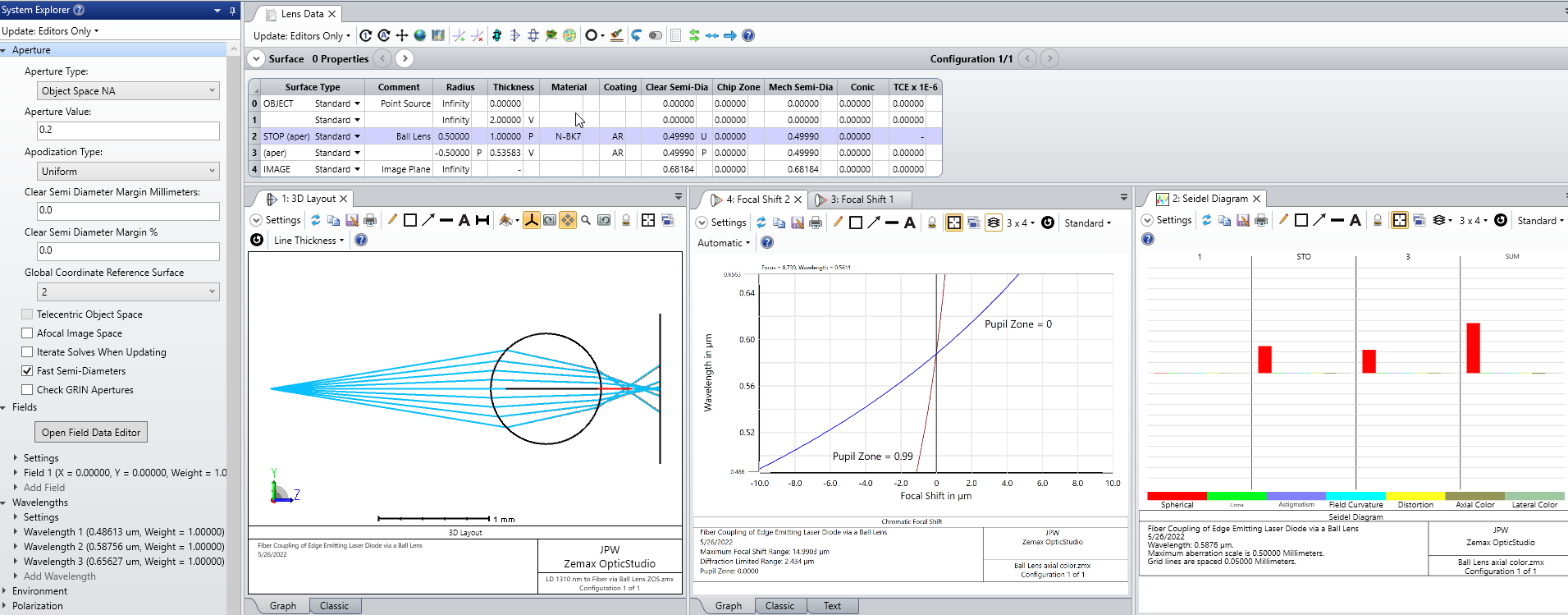
I was thinking that you were using a ball lens in a more conventional way. From your ray trace layout it looks like a more complicated component. Here is a layout I put together using a simple BK7 ball lens with an on-axis point source.
There is substantial spherical aberration. It dominates over the axial color. In this case the axial color, or chromatic focal shift, is actually smaller for the marginal ray (pupil zone = 0.99) compared to the paraxial ray (pupil zone = 0).
I’m not sure what is happening with your layout. I would need to see the model file before I could provide meaningful feedback.
Regards,
Jeff
Hi Jeff,
Yes, for the on-axis system, I also did a testing and got a similar result as yours.
I attach my off-axis system file for your check. Thank you.
There are a few important issues in your model that need correction:
1. The stop surface (and hence, in this case, the entrance pupil) is only 0.01 um from the object surface -- better to move it farther away. Note, the source rays are launched so as to sample the entrance pupil. 2. Both of the objects in the NSC group are touching the entrance port -- this is not allowed. (check the help documentation, objects cannot touch either the entrance or exit ports) 3. The exit port z-axis is not aligned with the outgoing chief ray -- add a coordinate break surface and then use chief-ray solves to force alignment.
The last issue is the one that most dramatically affects the axial color calculation because OpticStudio finds the image plane for each wavelength (at a given pupil zone) relative to the optical axis. This is done by tracing real marginal rays when the pupil zone > 0. The axial color is the separation between these image planes as measured along the optical axis. If the optical axis is not properly defined, then the resulting image plane locations are essentially meaningless.
I’ve gone ahead and fixed these problems in the attached model. As you can see, the axial color plots are now much better behaved.
There are a few important issues in your model that need correction:
1. The stop surface (and hence the entrance pupil) is only 0.01 um from the object surface -- better to move it farther away. Note, the source rays are launched so as to sample the entrance pupil. 2. Both of the objects in the NSC group are touching the entrance port -- this is not allowed. (check the help documentation, objects cannot touch either the entrance or exit ports) 3. The exit port z-axis is not aligned with the outgoing chief ray -- add a coordinate break surface and then use chief-ray solves to force alignment.
The last issue is the one that most dramatically affects the axial color calculation because OpticStudio finds the image plane for each wavelength (at a given pupil zone) relative to the optical axis. This is done by tracing real marginal rays when the pupil zone > 0. The axial color is the separation between these image planes as measured along the optical axis. If the optical axis is not properly defined, then the resulting image plane locations are essentially meaningless.
I’ve gone ahead and fixed these problems in the attached model. As you can see, the axial color plots are now much better behaved.
Regards,
Jeff
Hi Jeff,
You are right. The optical axis alignment causes the problem. I read the online tutorial of Coordinate break before, and I should have noticed that earlier. I should also learn more about optical design but not just software.
I really thank you for solving the problem for me.
No problem, glad to help. Mastering the many facets of optical design takes time. The best way to learn is to roll up your sleeves and go work on problems, just as you are doing. Good luck with your current project!