Solved

catadioptric objective issues?

  • 6 February 2024
  • 3 replies
  • 56 views

Userlevel 1
Badge

Hello guys.

    I’ve been working on a high NA objective for the semicon metrology. A catadioptric lens is recommended. See the layout below,


catadioptric layout

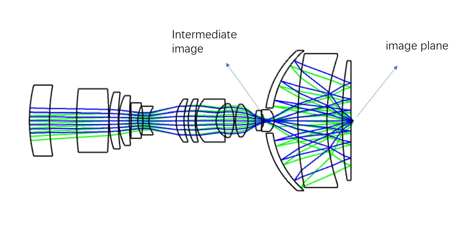
the EFFL calculated by ZEMAX is -4 mm. From what i can see, it’s an imaging system, the focal length should not be a minus value. Can anyone explain this?

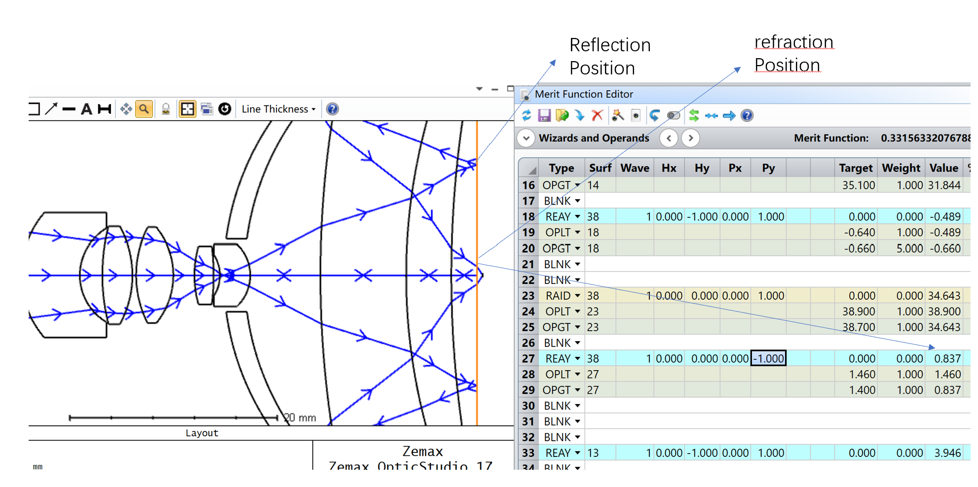
and when I use the operand REAY to calculate the real ray coordinate at the image-1 surface, it went wrong. Is REAY not applicable in this kind of  catadioptric lens?  


icon

Best answer by Andrey.Pravdivtsev 8 February 2024, 10:34

View original

3 replies

Userlevel 3
Badge

You have an intermediate image plane so the sign was changed. Your system has positive power so don’t worry.


REAY should work good there. What message did you get?

Userlevel 1
Badge

@Andrey.Pravdivtsev 

Thanks, Andrey.

  1. I’m going to find the relationship between the focal length sign and the intermediate image.

       Opticstudio usermanual doesn’t have the convetion, maybe you can recommend a book              which I can read.  


       2. As for the REAY operand, see the picture below

    because of the catadioptric structure, rays reflect at the surf38 first and then pass through the surf38 , the REAY operand tells the refraction position only.  How can it tell the reflection position also? Should a dummy surface be involved,I guess?


Userlevel 3
Badge

Hi,

  1. It can be internal Zemax sign convention. Sign change every time you have an intermediate imape plane. Or you can look on the sign of max field point.
  2. Yes, you are correct, you need to set a surface there. For a design with a mirror in sequentional mode it is common to have several components for the same surface (for example Mangin mirror). 

Reply