Hi,
I am having issues with the resulting CAD model of my optical design. I have created a generic example below to reproduce my problem.
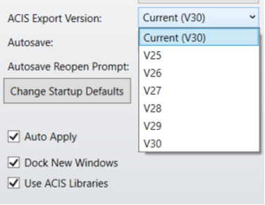
I use the below parameters. (using software V20.3)
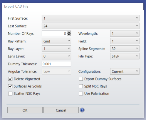
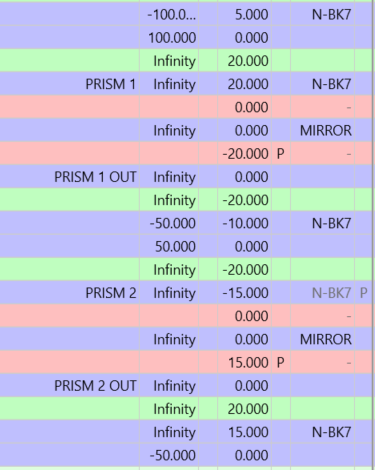
The full design is below, 3 lenses and 2 prisms, including some negative distances/thicknesses as I am changing the coordinates with the mirrors.
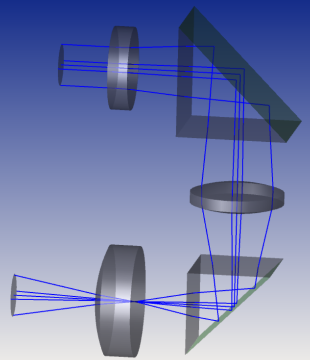
However, when opening the CAD model , there are errors:
- The “negative” surfaces don’t show (no lens in the middle and one surface of each prism missing). How can I fix this?
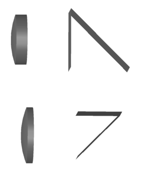
-
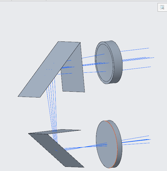
CREO (assembly mode) - Furthermore, in “part” mode in Creo, all the lenses are squashed together in a single place (and still no negative ones). How can I fix this?
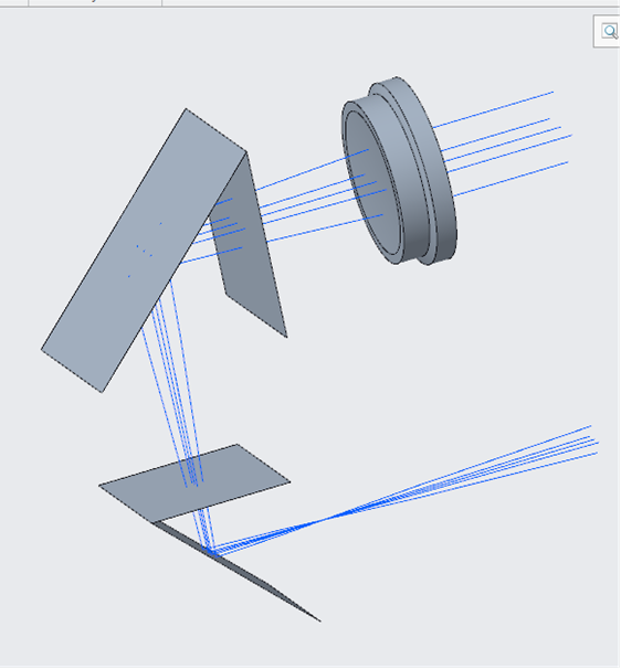
I can share the Zemax file if you need, but I dont think I am doing something too complicated? Can the CAD not deal with coordinate breaks?
Thanks for your help,
Regards.
Audrey.


