Solved

CAD file not exporting negative distances, or showing surfaces squashed together

  • 6 October 2022
  • 4 replies
  • 208 views

Hi,

I am having issues with the resulting CAD model of my optical design. I have created a generic example below to reproduce my problem. 

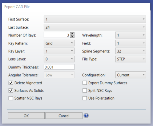
I use the below parameters. (using software V20.3)


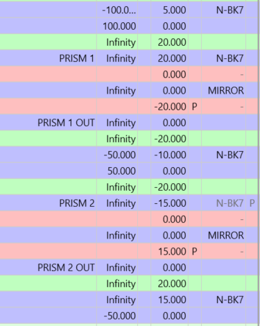
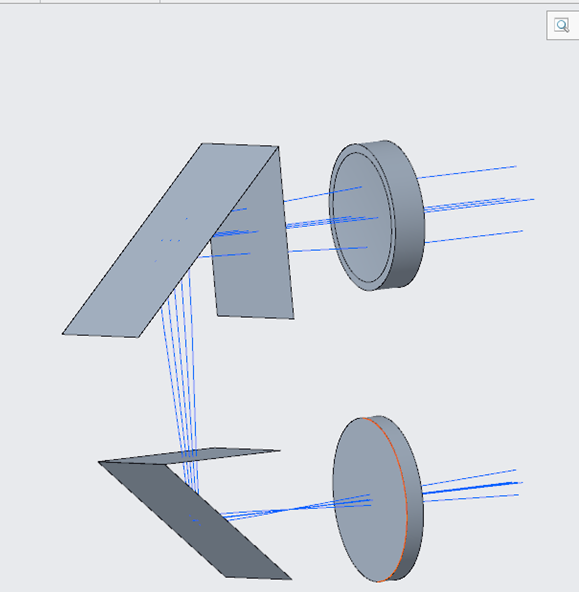
The full design is below, 3 lenses and 2 prisms, including some negative distances/thicknesses as I am changing the coordinates with the mirrors. 


Zemax 3D/Shaded model


Zemax lLens data


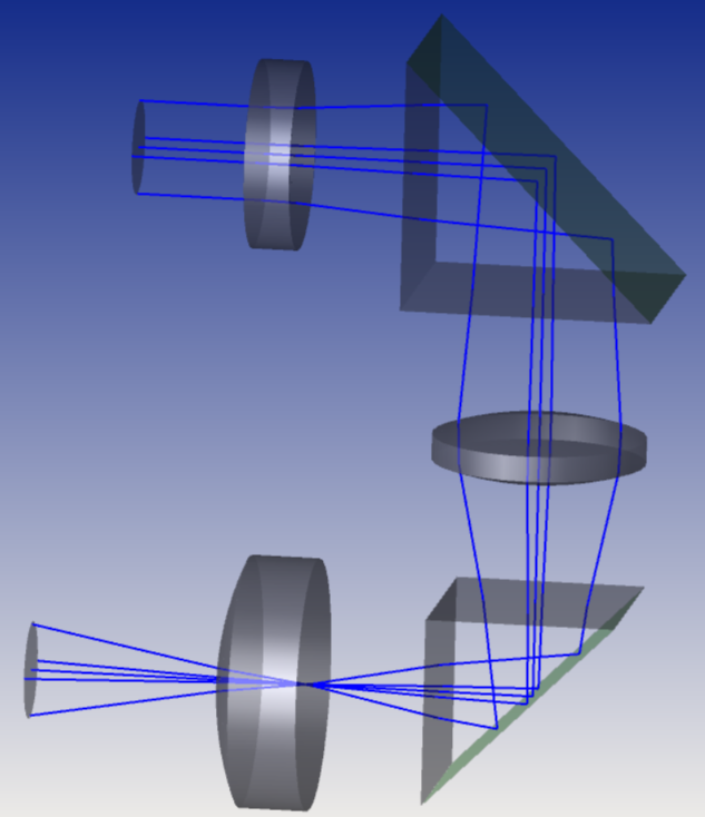
However, when opening the CAD model , there are errors:

  • The “negative” surfaces don’t show (no lens in the middle and one surface of each prism missing). How can I fix this?
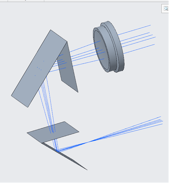
ZEMAX Object Explorer
  • CREO (assembly mode)


  •  
  • Furthermore, in “part” mode in Creo, all the lenses are squashed together in a single place (and still no negative ones). How can I fix this? 
CREO (part mode)
  •  

I can share the Zemax file if you need, but I dont think I am doing something too complicated? Can the CAD not deal with coordinate breaks? 


Thanks for your help,

Regards.

Audrey.


icon

Best answer by Sandrine Auriol 12 October 2022, 14:15

View original

4 replies

Userlevel 2
Badge

Sir, try reducing the subsegments of your components in the LDE and then try to export. Let me know if that worked.

Userlevel 6
Badge +2

I would recommend not using the ACIS libraries (untick) and see if that works. If you untick them, you will be back to the SMS libraries.

We are working on new CAD libraries to no longer use the ACIS libraries.

Badge

Hi Sandrine, the untick ACIS libraries did not work.  Currently we are using Zemax 20.3.1 and when we try to export a lens starting with a negative distance Zemax only exports the surfaces, even when the “Surfaces As Solids” is ticked.

Userlevel 6
Badge +2

Hi @Audrey.Aitken! Can you please share the file and I’ll have a look.
If you prefer to send it to the support, email support@zemax.com

Thank you.

Reply