Solved

Biconic Zernike surface producing incorrect results.

  • January 29, 2024
  • 1 reply
  • 171 views

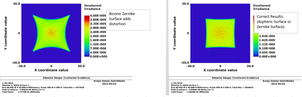
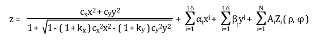
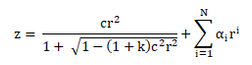
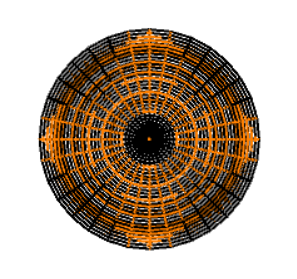
I have an asphere lens setup in NSC, and want to see the effect of adding an astigmatism to the lens. The only way I see is to use the biconic Zernike surface with all Zernike coefficients set to 0. When enter the lens prescription into the aspheric surface or Zernike surface, I get the correct results. As soon as I switch to the biconic Zernike the results look incorrect. Any ideas on why they do not match?
 

Spot at 100mm


Best answer by mojtaba.falahati

Hi Chris,
 
I already emailed you the response, but I post it here as well in case other users come up with the same question.
The Biconic Zernike Surface is described by the following sag equation:
 
?name=image.png
which is not necessarily the same as the Aspheric surface sag given the higher order aspheric terms (X^4 and Y^4 in your model):
 
?name=image.png
This can be seen by superposition of the two surfaces in the 3D Layout:
 
?name=image.png
That's why the illumination patterns are different with Biconic Zernike and Aspheric Surfaces.

Best regards,

Moj

View original
Did this topic help you find an answer to your question?

mojtaba.falahati
Zemax Staff
Forum|alt.badge.img+2

Hi Chris,
 
I already emailed you the response, but I post it here as well in case other users come up with the same question.
The Biconic Zernike Surface is described by the following sag equation:
 
?name=image.png
which is not necessarily the same as the Aspheric surface sag given the higher order aspheric terms (X^4 and Y^4 in your model):
 
?name=image.png
This can be seen by superposition of the two surfaces in the 3D Layout:
 
?name=image.png
That's why the illumination patterns are different with Biconic Zernike and Aspheric Surfaces.

Best regards,

Moj


Reply


Cookie policy

We use cookies to enhance and personalize your experience. If you accept you agree to our full cookie policy. Learn more about our cookies.

 
Cookie settings