Beam splitter


Userlevel 1

Hi all,


I am trying to simulate beam splitter , and i am using the file at zemax/samples/non-seq/ray splitting as reference.


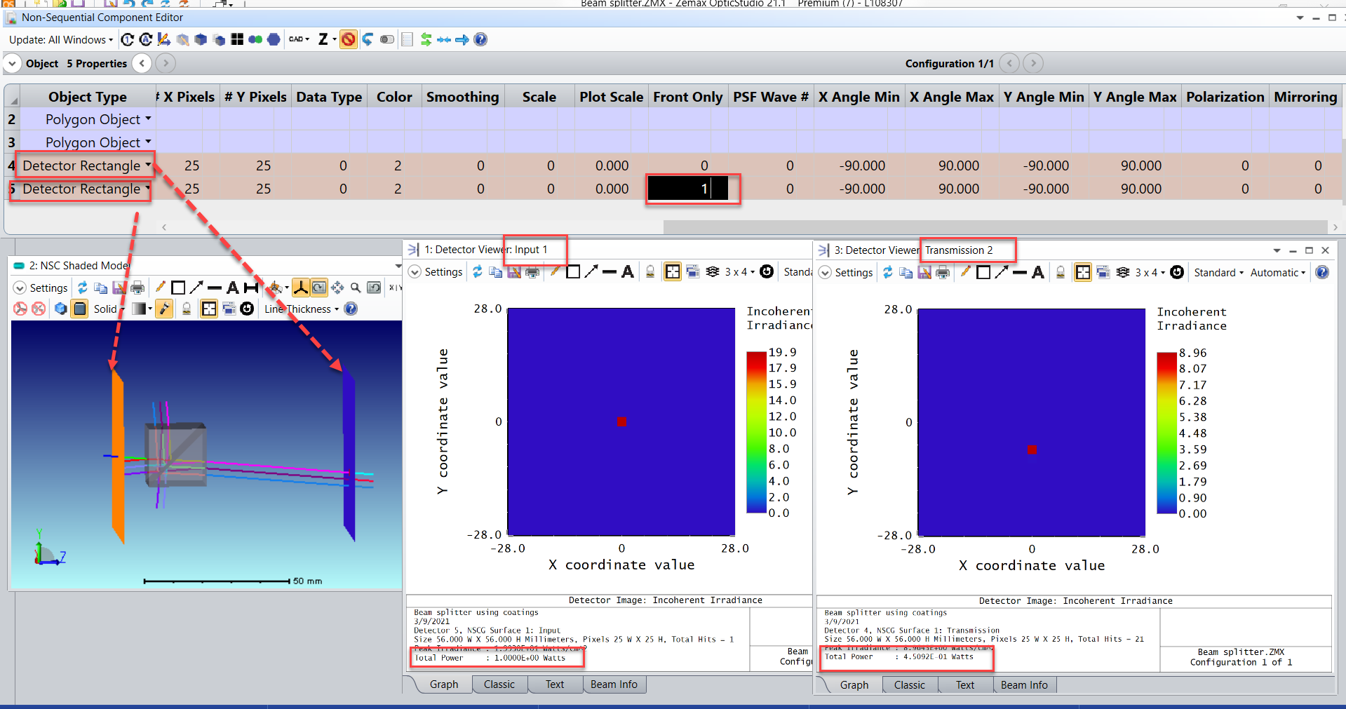
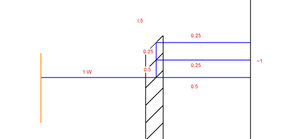
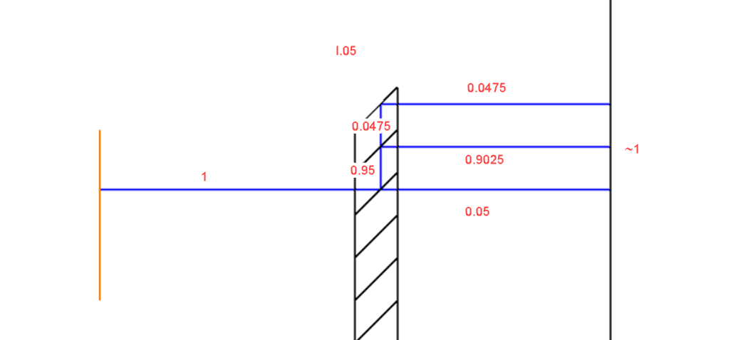
I am intrested mostly in finding the ratio between the transmitted intensity  through one of the ports to the initial intensity .


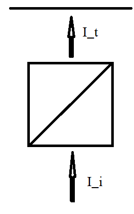
How i relate the transmitted data in the detector viewer to the initial intensity? (I_t/I_i)


Thanks,


Nadav


12 replies

Userlevel 4
Badge +1

Hi Nadav,


What you can do is to place a Detector after the source beam and turn on its Front Only flag. This way the detector will only register the power of the source ray when it's first being launched towards the detector. This will then be your input power. After that you can place another detector after the beam splitter to capture the transmitted power, as shown below. 


I've attached this sample file here for your reference.


Best regards,


Hui

Userlevel 1

Hi Hui,


Thanks for the help!


 I saw that you also delete the first source as 'absorber' material.


I now want to simulate array of beam splitters with a plane wave(ensemble of rays with the same direction) and find the transmitted power.


How do I define such source?


Thanks,


Nadav


Userlevel 6
Badge +2

Hi Nadav,


The Source Ellipse in Hui's file is a good representation of a plane wave. So you could simply make your Source Ellipse bigger.


Then if you prefer, there is an array option inside the Source properties. 


Does that answer your question?


Sandrine

Userlevel 1

Hi Sandrine,


edit: find the problem


****


I changed it to source rect-it's look good now.


I am attaching a file when I do not get ray splitting at all.


What did  I forget to define?


*****


Thanks


Nadav

Userlevel 6
Badge +2

Hi Nadav


I am not sure what you'd like me to check. Here is what I have:


Is it what you expect?


Sandrine

Userlevel 1

Hi Sandrine,


Yes it is what I expect. I thought the split NSC rays is the default in the full Non Sequential mode.


Another questions regarding the NSC:


I lunched a some rays into the system and trace them, they arrived to the detector, but I saw no signal on the detector.


What could be the reasons for that?


Thanks,


Nadav


Userlevel 6
Badge +2

Hi Nadav,


There are a few reasons this might happen. The two most common are listed below. 


1. To see results on the detector, you must use the NSC Ray Trace tool under the Analyze tab. The NSC Ray Trace uses the Analysis Rays of the source, not the Layout Rays. What you see on the layout provides an idea of how the rays will trace through the system, but what is actually traced happens behind the scenes. The detector will not update until that full, behind-the-scenes ray trace is complete. 


2. The orientation of the detector may be affecting the results. First - confirm you have run a ray trace and are analyzing the correct detector in the Detector Viewer. If you have confirmed these points and are still seeing a blank screen, then the detector may be 'backwards'. In the Non-Sequential Component Editor, there is a parameter for the Detector Rectangle titled Front Only. If this is set to 1 then the detector will only analyze the results striking the front-face of the detector. 


Let me know how this advice works for you. If you still see no results, please send me the file as a Zemax Archive (ZAR). You can do so publicly here, or in private through a case. 


Best,


Allie

Userlevel 1

Hi Allie,


Yes, it worked. Thanks!


I had another problem when simulating array of beamsplitter(50% and 5% transmission):


The output power is 0.97% on both cases.


Attached here the two files with the beam splitter polygon file.


Thanks,


Nadav

Userlevel 6
Badge +2

Hi Nadav


I think this is because of the way the polygon object is oriented. Click on View Current Object:


So it seems to me like it should be the face 0, the splitter. 


But your polygon object doesn't look quite right to me either. I think you forgot to define one rectangle. I would also check the face assignement.


Let me know if that is enough to get you in the right direction.


Sandrine

Userlevel 1

Hi Sandrine,


Thanks for locating the missing surface but i am not sure this is the source of the problem.


I want the red surfaces to be the beam splitters. Didn't I define them correctly?


Thanks,


Nadav


Userlevel 3
Badge +2

Hi Nadav,


I think you are having roughly the same power in the detector for both cases because of the internal reflections. For the first case (Coating I.50) and ignoring the losses to simplify the concept, it would be something like this:


Note that at the top, there is Total Internal Reflection and all the power is reflected towards the detector. If now you change the coating to I.05, the transmission of the beam splitter surface is lower, but the rest of the energy is reflected and it also ends reaching the detector:


Userlevel 1

Hi Berta,


Thanks for the help!


Best regards,


Nadav

Reply