Beam Parameter Product Different in Slow/Fast Axis Compared to Research Study

  • 24 August 2020
  • 5 replies
  • 213 views

Userlevel 5
Badge +1

This thread is a continuation from the forum posts linked here: https://my.zemax.com/en-US/forum/threads/2ff09cf1-4edd-ea11-a813-000d3a329613#


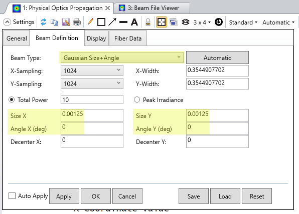
Thank you for your valuable response. I have calculated the value of the BPP in the X-axis (slow axis) that is 0.874 mm mrad and in the Y-axis (fast axis ) is 22.3mm mrad.


But my main concern is that the value of the  BPP in the fast axis is much more than the slow axis. 

The same problem is also occur during the calculations from the Spot Diagram. I also attached a research study in which you can see the values of slow and fast axis after collimation.  I hope, now you can understand the difference.


5 replies

Userlevel 5
Badge +1

Hi Neha,


Thanks for the added information, especially regarding the research study whose results you provided. To clarify on those results, are the 'Parameters after collimated' values based on results after both the fast and slow axis are collimated? Would this be a result of the Paraxial XY surface?


This is mostly just to make sure that you're setting up the model according to your physical setup. The reason for this is that because those numbers are from a research study, I am wondering if part of the performance measured after collimation is due to any impacts the collimating optics might have. When you use something like a Paraxial lens, it won't impact the quality of the beam in any notable way (unless the Paraxial lens is too fast for POP or other general OPD computations). So, I am not sure if the results would match up necessarily in this setup.


As another way to set up your POP system, you might be able to use the 'Gaussian Size+Angle' definition to sidestep the Paraxial setup. That way, you could directly define the beam characteristics based on your datasheet (as you can even separate the X and Y definitions):


This would mean that you would want to not trace through the Paraxial XY surface in its current definition. However, this still leaves the question of 'collimation,' which I am still unsure of whether this takes place prior to or after the ball lens. If it's after the ball lens, then you could use the POP output at the Image surface to see what your new beam parameters are after passing through it. If the collimation takes place prior to the ball lens, then you'll need to define a new Paraxial surface or real lens which will collimate this POP beam to your needs (still checking to make sure that it doesn't break the algorithm assumptions). Again, if you use the Paraxial XY lens, no aberrations will be imparted onto the beam, which could make comparisons like these less in agreement. You could add in surfaces like a Zernike Standard Phase surface to introduce some error to your POP beam, or if you use a real lens, you could see if the inherent aberrations in that element match up close enough with your results.


Please let us know how these thoughts work out for you, and I hope you have an excellent rest of your day!


~ Angel

Hello Angel,


Thank you for an appreciable response. I want to check, how much values get decreased after the collimation. So, we can calculate the BPP for the fast and slow axis. Please see the link for clear the things https://www.researchgate.net/publication/309300574_Design_of_150W_105-mm_022NA_fiber_coupled_laser_diode_module_by_ZEMAX#read


In the above link, they used different lenses as a FAC and SAC. but I am using a single ball lens for collimation of beams. 

Userlevel 5
Badge +1

Hi Neha,


Thanks for your additional details and link to the research article. Your comments and paper definitely clear things up for me.


I think what's needed here is some control not just for the divergence angle of your beam, but also the size of the spot itself (since the BPP is a product of the beam waist diameter and divergence angle). So, prior to the beam entering the ball lens, you'll likely want to have a dummy surface to evaluate the distance after the Paraxial XY surface needed to achieve the correct beam diameters, which would be separate from the divergence angle. Then, this dummy surface would essentially act as the 'emitting' surface of the diode you are using (rather than the field point prior to the Paraxial lens). For an example on how to perform an optimization at an intermediate surface (and even trying to consider both a spatial requirement, like spot size, on one surface, and an angular requirement, such as collimation, on another surface), I'd recommend looking at this Knowledgebase article.


This is likely one reason why even the geometric ray setup wasn't giving you some expected values, but there might also need to be some tweaking/optimization done to have POP obtain similar results. Alternatively, you could define an asymmetric beam in POP with the same characteristics as in your paper to begin propagation from this dummy surface, sidestepping the need for the Paraxial XY within the POP run but still retaining it for your geometric tracing needs.


If you'd like to get into more details for your specific model, I would encourage you to open another case with us through MyZemax so that we can discuss your system one-on-one rather than on this forum. Thanks!


~ Angel

Hello Angel,


Thank you for your response. I have added the intermediate surface to control the spot size but no change in the calculation. still, the value of BPP in the y-axis is greater than the x-axis. I hope, you will help me with the appropriate calculation.

Userlevel 5
Badge +1

Hi Neha,


Thanks for your post here! I just wanted to notify you that we have followed up on your MyZemax case. If you have any further questions that you feel can be discussed in the public forum here, please don't hesitate to reply to this thread. Otherwise, we can continue discussion on your case itself.


Thanks!


~Angel

Reply