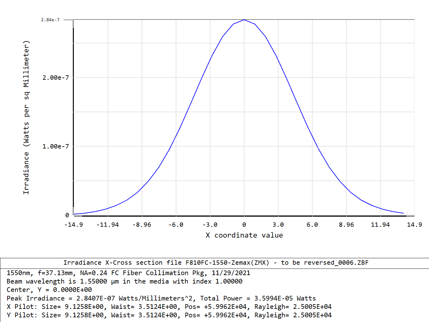
Hi all,

I would like to ask some basic questions about the fiber coupling.

In the zemax Help file, it is said that the total coupling efficiency is the product of the system efficiency and the receiver efficiency. What is the receiver efficiency? Which factors will affect the receiver efficiency? i.e., how to increase the receiver efficiency?  Thank you in advance.

All the best,

YJ

You might find it useful to read this article: Single-mode fiber coupling in OpticStudio.

It describes both the system efficiency S and receiver efficiency T in mathematical terms. Basically, the system efficiency describes the fraction of energy at the entrance pupil which is delivered to the fiber input, and the receiver efficiency describes the fraction of that energy which matches the mode of the fiber. The coupling efficiency is the product.

For a single mode fiber, receiver efficiency is maximized by presenting the fiber input with radiation forming a Gaussian waist that matches the mode field diameter of the fiber.

To add a little more: In designing optics coupling two single mode fibers with the same mode field diameter we need a magnification of one to preserve the mode field diameter, and minimal aberrations to preserve the Gaussian profile. Coupling fibers of different diameters requires an appropriate magnification and minimal aberrations.


Hi David, thank you for your timely and enlightening reply.

Here is my question. I used a pair of collimator and coupler and tried calculating the coupling efficiency. When the distance between the collimator and coupler increased to e.g. 60 meters, the coupling efficiency decreased to 0.32 when polarization is not taken into account ( system efficiency of 0.88 and receiver efficiency of 0.37) and to 0.1 given polarization (system efficiency of 0.28 and receiver efficiency of 0.37).

Then I checked the M2 and it increased to ~10, i.e., it deviated far from the Gaussian beam at a distance of 60 m. In this case, what I can do to increase the  receiver efficiency, to meet the criterion you mentioned “by presenting the fiber input with radiation forming a Gaussian waist that matches the mode field diameter of the fiber”?

Besides, I didn’t get it by “a magnification of one to preserve the mode field diameter, and minimal aberrations to preserve the Gaussian profile”. Which operation needs to be done exactly?

Looking forward to your enlightening reply again. : )

Regards,

YJ


p.s.: please click the link to open the .zar file

https://cloud.tugraz.at/index.php/s/foD3wFrTJZHackM


Hi YJ,

I took a look at your file. I don’t think you’re reading the results correctly.

For fiber coupling without accounting for polarization I see:

  System 0.999999, Receiver 0.950921, Coupling 0.950921

Accounting for polarization:

  System 0.322407, Receiver 0,955296, Coupling 0.307994

Generally, the most important thing that considering polarization does is cause Fresnel reflections to be modeled. This looks like only 32% of the radiation is making it to the receiver, but that which does couples well to the fiber mode. The most obvious suspect is reflections from the air-glass interfaces.

Running a transmission report confirms this:

Field Pos : 0.0000 (deg)
  Transmission at    1.5500:        0.324212919
  Transmission at    1.4900:        0.305541476
  Total Transmission       :        0.314877198


Chief Ray Transmission Surface By Surface:

Field Pos : 0.0000 (deg)
Wavelength 1: 1.550 µm

 Surf        Tot. Tran        Rel. Tran
   1         1.000000         1.000000
   2         0.815600         0.815600
   3         0.664695         0.814977
   4         0.614032         0.923779
   5         0.566588         0.922735
   6         0.523402         0.923779
   7         0.482961         0.922735
   8         0.393903         0.815600
   9         0.321022         0.814977
  10         0.321022         1.000000

Field Pos : 0.0000 (deg)
Wavelength 2: 1.490 µm

 Surf        Tot. Tran        Rel. Tran
   1         1.000000         1.000000
   2         0.803808         0.803808
   3         0.645716         0.803321
   4         0.596397         0.923622
   5         0.550351         0.922793
   6         0.508317         0.923622
   7         0.469071         0.922793
   8         0.377043         0.803808
   9         0.302887         0.803321
  10         0.302887         1.000000

So I think you have a good design, except that the coatings are reflective at your wavelengths. A Coating analysis for surface 2 which has THORA on SFL6 confirms 80% transmission for the surface.

Looking at Thor Labs web page for this part confirms THORA is a visible AR coating. I think you want THORC.

Here’s a link: Thor Labs

This might have been an error in the library part you loaded.

With THORC coating, the coupling is increased to 69%. So you in fact have a pretty nice design!

I attach the ZAR file in a ZIP.


In regard to the two questions I didn’t answer:

Magnification: For coupling a source fiber to a receiver fiber where each have the same mode field diameter, the nominal design of the coupling optics would have a magnification of 1 to image the Gaussian waist at the output of the source to the input of the receiver. If the receiver had twice the MFD, the nominal design would have a magnification of 2. This would also result in reducing the NA to match the receiver.

Aberrations: To get a good quality Gaussian at the receiver we need minimal aberrations. A diffraction limited design is best.

In designing coupling systems, it is best to design a diffraction limited system first, using ordinary sequential design methods. You are trying for a diffraction limited system with an Airy disk comparable to the MFD of the receiver. Then do a final optimization using fiber coupling.


“Looking at Thor Labs web page for this part confirms THORA is a visible AR coating. I think you want THORC.

Here’s a link: Thor Labs

This might have been an error in the library part you loaded.

With THORC coating, the coupling is increased to 69%. ”

Yes, David. I can’t agree with you more than enough!!! Thank you SO much! The measurements are also consistent with this value!

Second, I don’t think I have explained the issue clearly. In fact, I didn’t read the data wrong. The above result is for the distance of 1.5 meters, which corresponds to the default thickness for Surface 5 in the LDE. When the distance is small, the result is really good.  My question is as follows:

When the distance increases, for example to 60 meter, i.e., the thickness for Surface 5 in the LDE is set to 60 000, the result is (given polarization):

system 0.646995, receiver 0.380516, coupling 0.246192

Likewise, when it increases to 100 meter,

system 0.444449, receiver 0.267726, coupling 0.118991

….

As shown, with the increase of the distance, both the system efficiency and the receiver efficiency are deteriorating, especially the receiver efficiency, and consequently the coupling efficiency decreases greatly.   At this time, the beam is no longer Gaussian beam, but with many side lobes, as can be seen from the irradiance distribution. This is consistent with what you said previously “...For a single mode fiber, receiver efficiency is maximized by presenting the fiber input with radiation forming a Gaussian waist that matches the mode field diameter of the fiber...” 

So the question becomes “How to transform such a none-Gaussian beam at 100 m into a Gaussian one that matches the MFD of the fiber”.  I hope, I explained the question clearly this time. Maybe this is beyond the scope of OpticStudio, but I still wish, I could get some enlightenment from this community. : )

Looking forward to your reply!

All the best,

YJ


In regard to the two questions I didn’t answer:

Magnification: For coupling a source fiber to a receiver fiber where each have the same mode field diameter, the nominal design of the coupling optics would have a magnification of 1 to image the Gaussian waist at the output of the source to the input of the receiver. If the receiver had twice the MFD, the nominal design would have a magnification of 2. This would also result in reducing the NA to match the receiver.

Aberrations: To get a good quality Gaussian at the receiver we need minimal aberrations. A diffraction limited design is best.

In designing coupling systems, it is best to design a diffraction limited system first, using ordinary sequential design methods. You are trying for a diffraction limited system with an Airy disk comparable to the MFD of the receiver. Then do a final optimization using fiber coupling.

In fact, you’ve already answered my question above to a certain extent. : )


Hi YJ,

I looked at results at 60m and reproduced your result. I placed a dummy surface 1mm in front of the receiving optics and looked at the POP result using the beam inspector. It appears that the beam is Gaussian as expected, but the beam divergence has expanded it to the point that it is clipped by the 20mm dia receiving optics. You might try a receiver design with an increased aperture.


“... the beam divergence has expanded it to the point that it is clipped by...” Yes, that’s it, David! Thank you for your confirmation! 

All the best,

YJ


Reply