Solved

Backward / Forward designs : TFT as "Tilted surface"

  • 15 November 2021
  • 3 replies
  • 303 views

Badge

Hi,

I have got question regarding backward/forward designs and the control of TFT Tilts.

Here is the case :

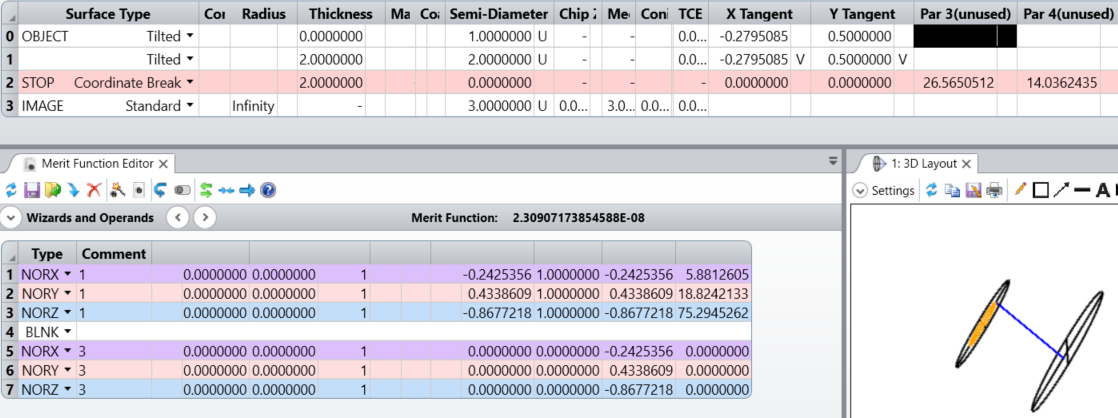
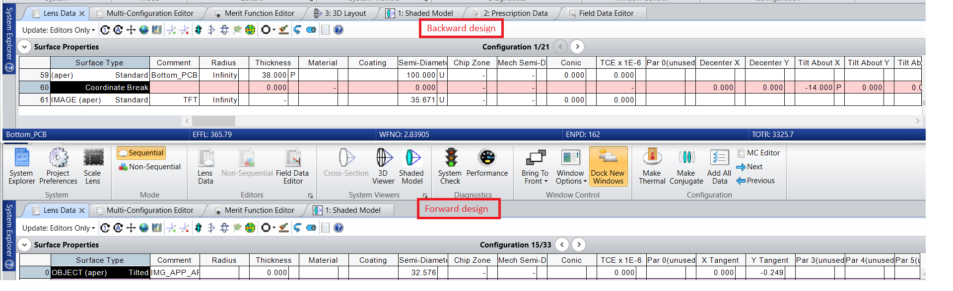
  • In backward design, TFT has two tilts : X Tilt and Y Tilt.
  • In Forward design, TFT is usually compute as a “tilted” surface type. When TFT has only one tilt (Tilt X, we put as Y Tangent value tan(Tilt X )). Then backward and forward designs are the same (to check we do a superposition of both designs in Catia). However, when TFT has two tilts (Tilt X and Tilt Y), we put as Y Tangent value tan(Tilt X ) and as X Tangent value tan(-Tilt Y). Then backward and forward designs are differents (no matter the sign of X Tangent. I have tried to change the order of the coordinate break surface controlling the Tilt X and Tilt Y in the backward design, without success.

Do you have a solution in order to have the same exact design for backward and forward ?

Best regards,

Nicolas

icon

Best answer by Kevin Scales 1 December 2021, 00:43

View original

3 replies

Userlevel 4
Badge +1

Hi Nicolas,

This raises a very good point. The Coordinate Break surface uses local coordinates, meaning that whether the order is normal (X then Y then Z) or reversed, it is always done with respect to the local coordinate system. Thus, after rotating about X, it then rotates about the new Y. The Tilted surface, however, takes a different formulation as seen by the formula z = Xtan(theta_x)+Ytan(theta_y), which is not fully local or global.

You could work out the differences in the rotation using matrices, but there is an easier solution, which is to let OpticStudio find the correct tilts for you. In the screenshot below, I have a tilted surface and a coordinate break, with the CB determining the desired angles. Then, using NORX, NORY, NORZ operands, I determine the surface normal in global coordinates of the CB and makes those numbers the targets for the Tilted surface. The variables are the inputs for the Tilted, and the system is optimized. As you can see, the result is similar, as expected for somewhat small angles, but not identical. You can see visually as well that the two are aligned. (The Object itself can’t be used in the operand, but the results are the same and can be put onto the object parameters.)


Badge

Hi Kevin,

Thank you for your answer. 

The thing is I do not want to have the OBJECT parrallel to the IMAGE. I want the OBJECT (=TFT) of forward design (from TFT to Virtual Image) to be in the same position as the IMAGE (=TFT) of backward design (from VI to TFT). Is this problem have a solution or maybe I do not understand well your point ?

Once again, thanks for your help


Best regards,

Nicolas

Userlevel 4
Badge +1

Hi Nicolas,

Having forward and backward designs match can be tricky with Coordinate Breaks and tilts. If the Reverse Elements tool does not work, it may be useful to use the Make Double Pass tool and then try to manually reverse signs starting at the second half, then removing the initial surfaces. This can be tedious, but if the tool to reverse the surfaces doesn’t produce the right answer, then some manual adjustment will be needed.

I’m sorry if I didn’t get at the point you were looking to address. From the question, it sounded like you mainly wanted to know how to make the tilts on a Coordinate Break match up with the tilts on a Tilted surface, which requires some adjustments because of their differing methods. The screenshot I posted shows how to use Optimization to get the NORX,Y,Z operands for different surfaces to match, namely by showing that the starting Tilted surface and the ending post Coordinate Break surfaces are oriented the same but with slightly different numbers for the rotation. The operands on lines 5-7 provide the direction cosines of the old Image surface, but it is lines 1-3 that have weight to them and are thus targeted to values read off from 5-7.

 In your case, you initially displayed a CB right before the final surface, with a sole purpose to tilt the image plane along one or more axes. The Tilted surface used as the Object matches those coordinates, but in your case you would then go ahead and remove the CB before the image so it is not parallel to the Object. I left them both there for verification purposes.

I hope this helps clarify what I meant while answering your question.


Reply