Hi there Zemax community,
I am coming here now in search of your expertise and help with a design problem that I am having.
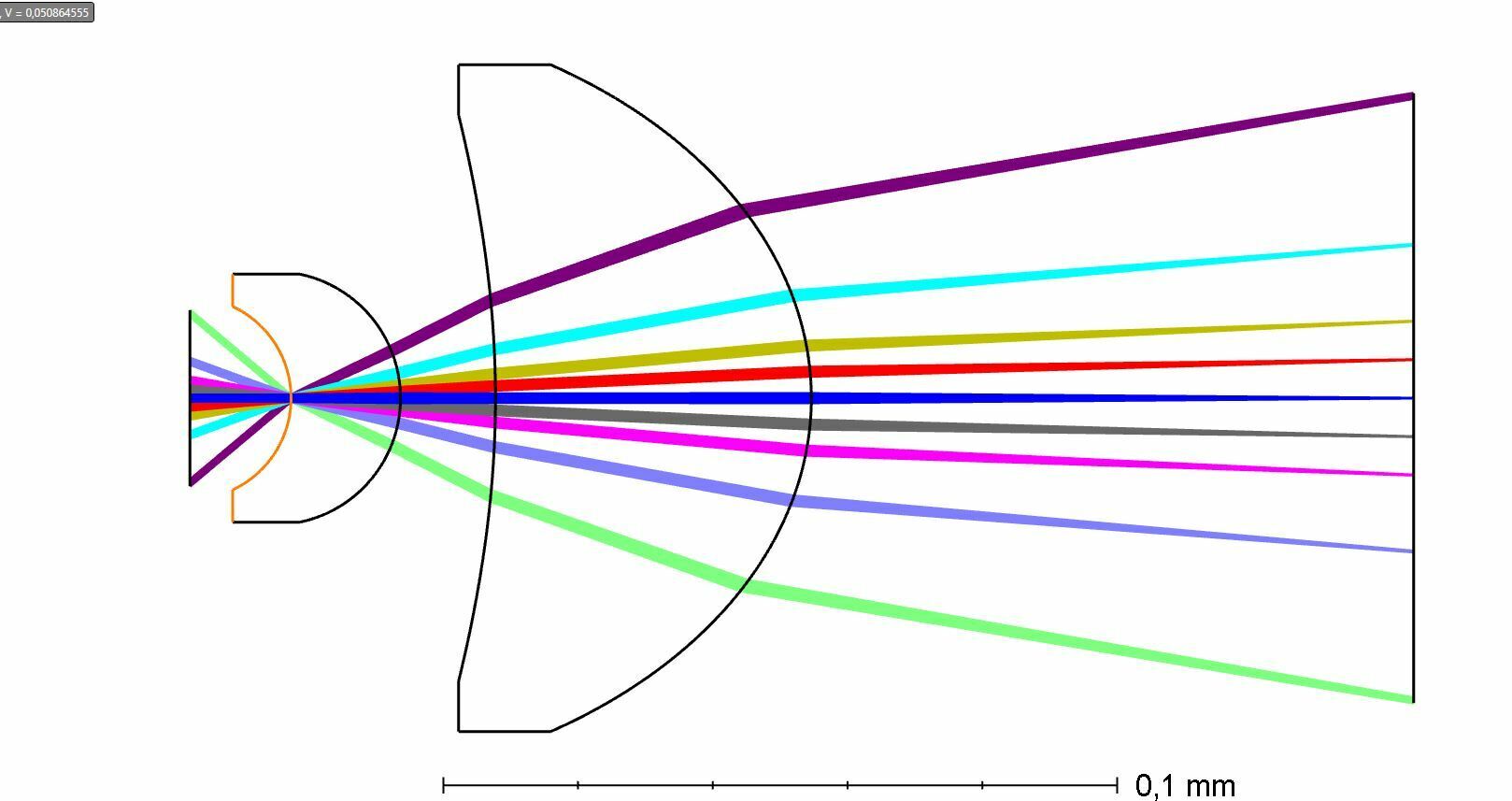
I have the following optical system which consists of a “quasi” solid immersion lens (Weierstrass lens) in combination with a singlet that generates a collimated output. Here I am just interested in the on-axis point so while optimizing this system, I just considered spherical aberrations and the overall angular deviations for the output wavefront in the afocal mode:
As you might guess from the title, I want to use image the back focal plane of this system. For me the question here is: Where is the back focal plane of this “objective”?
I found this arxiv paper in where they make an analysis of different commercial objectives used for doing back focal plane imaging:
https://arxiv.org/pdf/1507.04037
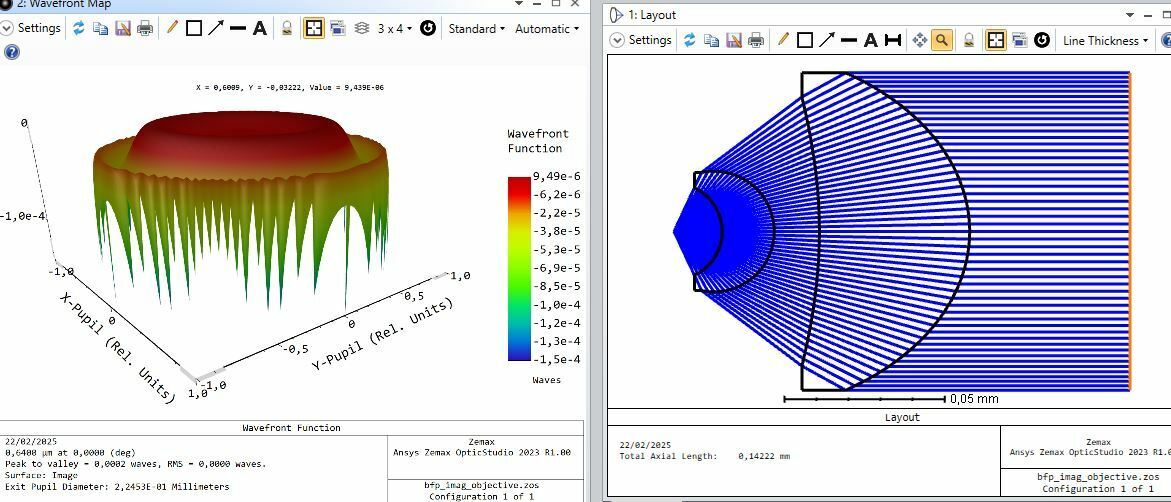
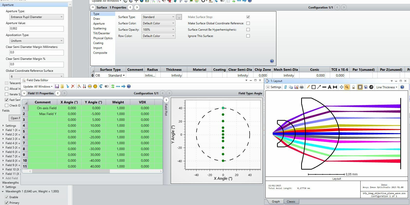
From figure 4 in the paper I can think that if I want to find the back focal plane, I need to change the source from being a point to plane waves coming from the object’s plane location and then finding the “plane” at which each one of these plane waves is in focus. When I try this for my system, this is what I got:
When I look at the “focus” for each plane wave, these are not all defined on a single planar surface. To me, it seems that there is a strong “field curvature” in this case. (I dont know if this can be thought as so here).
So here my questions are two:
-First at all, is my interpretation of the back focal plane correct in this case? Is this approach of using “plane wave” at the object plane correct? Can I just set the aperture type to entrance pupil diameter and set the diameter to a small value? (Here my aperture stop is just flat surface after the object space surface) How could I better extract details about the back focal plane for this “objective” configuration?
-My second point is: If this is a correct way to model the back focal plane imaging configuration, should I try to minimize the field curvature in this configuration here? Would this make sense? (So that I can have a planar image plane in this back focal plane configuration case)
Thanks a lot for the comments and feedback!!