Solved

Automatic Solve Error: Clear Semi-Diameter

  • June 1, 2021
  • 2 replies
  • 334 views

Forum|alt.badge.img

Hello everyone,

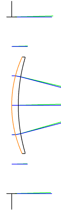
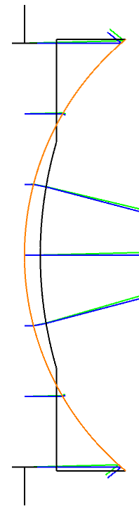
I am using clear semi-diameter setting as Automatic Solve to fill the aperture up with rays. While I select the solve type as automatic I get an unphysical surface layout (on the right side). With the default seetings I have a view as on the left side.

My aim is to correct this unphysical lens layout by retaining the initial focus.

I suppose this oddness on the right can easily be solved by a commonly known trick. I am open to your suggestions,

Thanks in advance.

Önder.


Best answer by Csilla Timar-Fulep

Hi Önder,

Thanks for your question here!

You can try to use the Edge Thickness Greater Than (ETGT) optimization operand to avoid this kind of unphysical lens layout:

You can set the radii of curvature and/or the lens thickness to variable, and optimize your system for e.g. RMS Spot size to achieve best focus with additonal ETGT operand to avoid the unphysical lens layout.

I hope this helps, but if you have any further questions, please ask!

Best,
Csilla

2 replies

Csilla Timar-Fulep
Zemax Staff
Forum|alt.badge.img+2

Hi Önder,

Thanks for your question here!

You can try to use the Edge Thickness Greater Than (ETGT) optimization operand to avoid this kind of unphysical lens layout:

You can set the radii of curvature and/or the lens thickness to variable, and optimize your system for e.g. RMS Spot size to achieve best focus with additonal ETGT operand to avoid the unphysical lens layout.

I hope this helps, but if you have any further questions, please ask!

Best,
Csilla


Forum|alt.badge.img
  • Author
  • Fully Spectral
  • June 1, 2021


thank you so much for your help Csilla!