Solved

Ask An Engineer: Laser diode and Fiber coupling question

  • 29 September 2022
  • 7 replies
  • 484 views

  • Single Emitter
  • 1 reply

Hi expert,

I want to simulate the focusing model (laser diode couple to fiber), and want to use FICL operand to optimize model.

But I don’t know how to set the Object space NA in the system and  Sna in the FICL. (Laser H_FWHM 18deg, V_FWHM 23deg)

If I have fiber MFD value, I can use the formulas NA=2*lamda/(pi*MFD) to set the Rna. And I right?
 

thanks,

C.L

icon

Best answer by Sandrine Auriol 8 February 2023, 20:27

View original

7 replies

Userlevel 6
Badge +2

Hi @C.L !

I was going through some of the unanswered questions on the forum and came across yours. I think this is a great question and wanted to answer it as part of our updated Ask An Engineer series! See my response in the video below:


Hi @Sandrine Auriol 
I just had a look to the video and I think a problem I had with my simulation could have a solution in the video. I have to simulate a system with a fiber output as a source in the simulation. The object space NA calculator that you used, doesnt come into my version of zemax(its an older one). Can you possibly tell how it is calculated or is there a equation in the manual to calculate it? 
I would really appreciate your healp on this 
Thanks
Mayank

 Hi again @Sandrine Auriol 
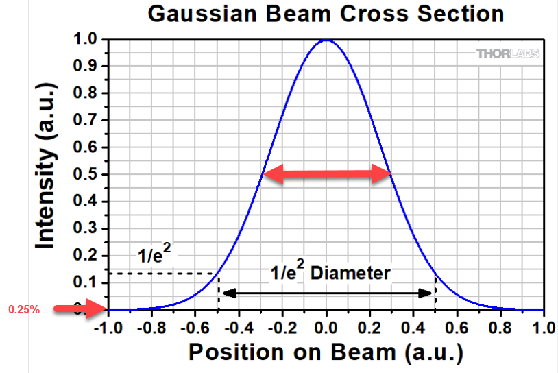
I also have one more question now, as far as the basic mathematics of a simple Gaussian distribution goes, What i was taught is that the width at half maximum(50% of energy drop) of a Gaussian profile is smaller than the width at  1/e^2(which accounts for 13.5% energy drop). the width being larger shouldn't it subtend a larger angle and hence a larger NA ? Also, when you calculated the object space NA, you got a large number of it(assuming that the marginal ray showed the 0.25% of energy) which explains my point that as the width of the profile becomes larger, the Na is larger.
The documentation says that the angle at 1/e^2 = 0.8.. X angle at FWHM which makes ângle at 1/e^2 value smaller and hence a smaller NA. I might be making a mistake in understanding something, It would be great if you could help me out 

Thanks in advance


Userlevel 6
Badge +2

Hi @Mayank1298!

The calculator that I showed is here: 

If it doesn’t work with your version of Zemax, check the source code. The formulas are in that file “ExtensionSettingsForm.cs”.

When I calculate the object space NA, I am specifying the energy of the marginal ray with the G value. So it would look like this:


So yes the biggest the G value is, the smallest the intensity of the marginal ray is and so the biggest the NA is.

Thanks- @Sandrine Auriol for the code and the explanation.
As from what I understood, the equation considers the FWHM (the full angle) and relates it to the the Half angle ( at 1/e^2 value) and therefore we see a decrease in the angle there by a factor of 0.8477. My bad, that I misunderstood your explanation in the video. 
About the code, I will try what you said and I think it should help :)
Regards

Userlevel 6
Badge +2

Glad it helped. Thank you!

Hi @Sandrine Auriol and other experts too who come across this problem that i have here
I know that the first question that I am going to ask is probably answered by many but I would still like to understand it better. I have a system of lenses to couple light from one fiber to another(passive) whose files I have attached to this question.
It consists of 2 aspheric lenses. the fibers that I want to use for coupling light from and into are SMF-28e which have a NA(e^-2) =0.09 and a MFD of 0.0046mm. Since I read some previous discussions and solutions from Zemax staff I used to user extension calculator to calculate the Object space NA for setting the system aperture for a apodization of 1. which gave me the same value of 0.09. setting that as the object space NA in the System explorer, I still find a difference in the POP and FICL calculations. to investigate more, I also tried to plot the FICL calculation for some system aperture values which I have attached below where it becomes stable at around a object space NA =0.167 where also it matches the POP calculations. Why is it happening if POP used the MFD which is at e^-2 value and my system aperture which plays a role in FICL calculation is also clipping the rays at e^-2 value when it is set to 0.09. Shouldn't  those give the same values to me? Why do I have to increase the NA to 0.167?


Secondly, I wanted to tolerance the system and therefore look at the effects of source fiber tilts/decenters and receiving fiber tilts/decenters. The POP allows me to just put  the source fiber decenter using the Beam data tab. where the input beam is decentered but doesnt allow me to tilt the source fiber. Therefore I go to FICL to do that, although the fiber tilt of eg:+5° is much different from what i get at  -5°. shown in the pictures attached. Since the system is having cylindrical symmetry, why do I see a change there, could anyone explain that ? For the receiving fiber however, it shows the same values for corresponding negative value of the tilt or decenter, no matter you use FICL or POP. Also for the source fiber decenteres the efficiency values are the same for corresponding -ve values of decenters. Could someone please have a look and help me out in understanding this ? 

Reply