Hello!
I’m reverse-engineering a system, and have come across some problems.
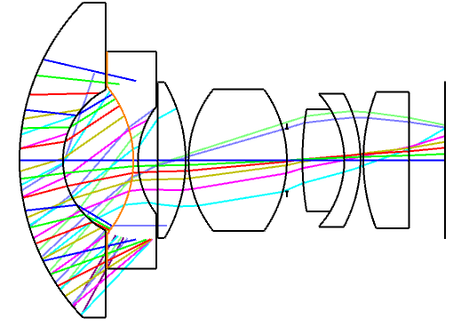
Why are the rays that are coming from the first surface stopping at the imaginary radius of surface 2 in the below image? The bottom part shows it more clearly.

Hello!
I’m reverse-engineering a system, and have come across some problems.
Why are the rays that are coming from the first surface stopping at the imaginary radius of surface 2 in the below image? The bottom part shows it more clearly.

Best answer by Christian Zimmermann
Hello Oscar,
unfortunately I don’t see the Lens Data Editor. Nevertheless I would say it has got to do with the “Clear Semi-Diamter” vs. “Mechanical Semi-Diameter” settings. Did you apply a certain amount of “Chip-Zone” to the surfaces? How about the vignetting settings shown in Field Data Editor? Have you got “Float-by-Stop-Size” or Image Space F/# defined as aperture of the lens?
Kind regards,
Christian
Enter your E-mail address. We'll send you an e-mail with instructions to reset your password.