
Angle of Incidence for Double Gauss 28 Degree Field

  • February 13, 2022
  • 6 replies
  • 1019 views

Hello everyone,

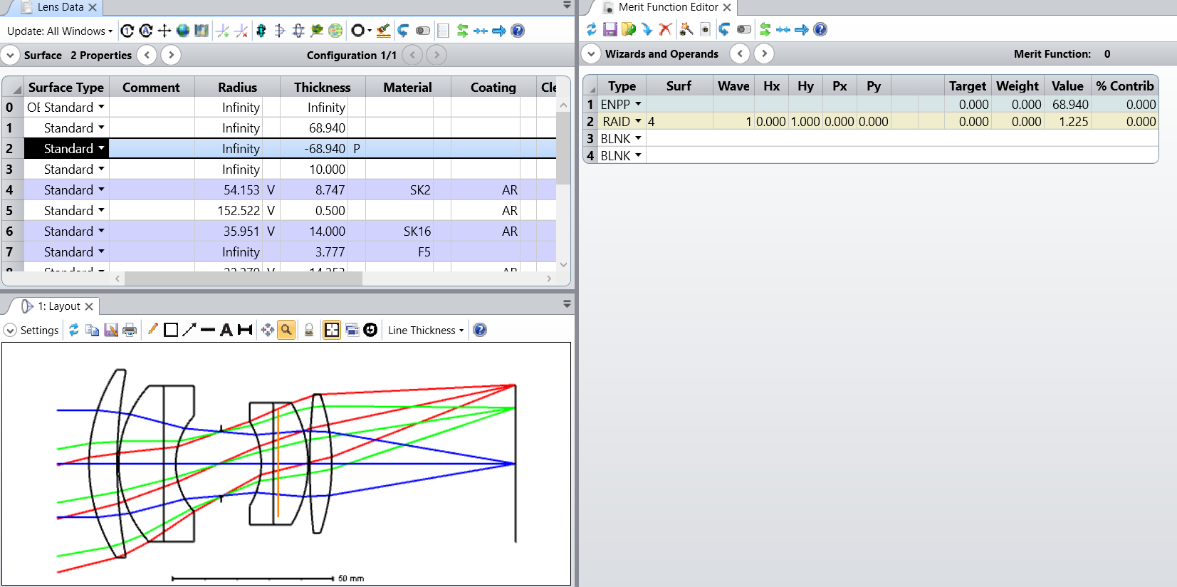
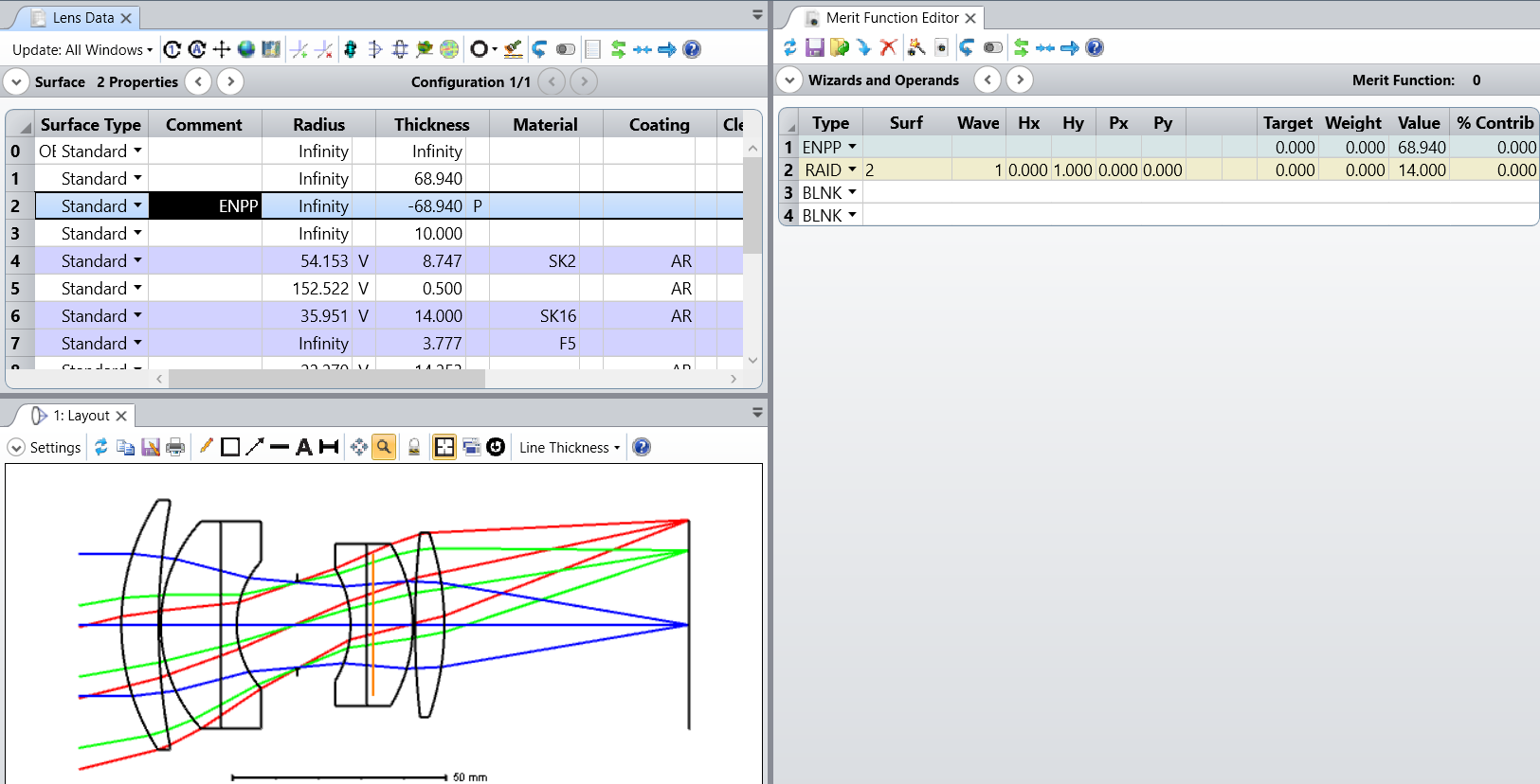
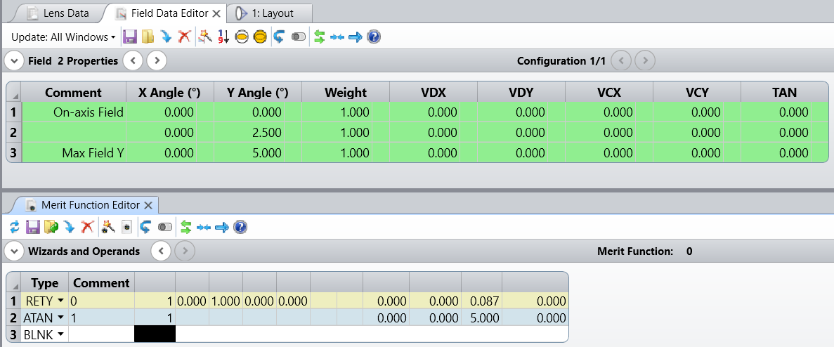
I am trying to see the angle of incidence on the merit function editor for a predefined field. My aim is to see the exact numbers that is defined by Field Editor field angle with the MFE using an appropriate operand. Although I tried a couple of them, on the MFE I couldn't manage to read the same value of angle in degrees as defined in Field Data Editor.


Samples->Sequential->Objectives->Double Gauss 28 degree field

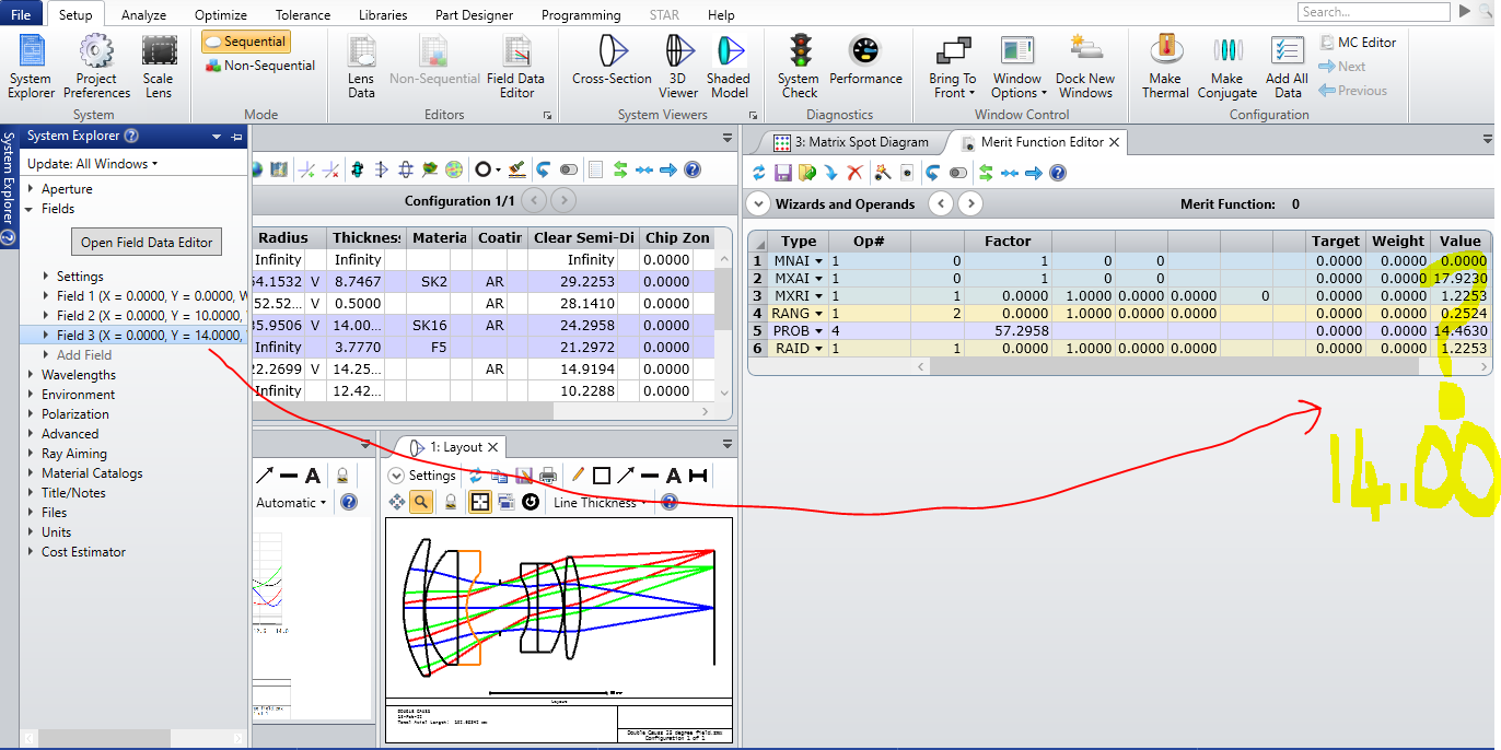
Can you please comment on this?

Regards,


Did this topic help you find an answer to your question?

6 replies

David
Luminary
Forum|alt.badge.img+4
  • Luminary
  • 337 replies
  • February 13, 2022

Hi Eda,

RAID (degrees) and RANG (radians) gives the angle between the incident ray and the surface normal. In your case the surface normal is not parallel the z axis.

From the help system

If you want to read the angle of incidence of the ray with respect to the z axis, you can insert a not tilted dummy surface with zero curvature and measure with respect to its surface normal, which is parallel the z axis:


Mark.Nicholson
Luminary
Forum|alt.badge.img+3

The field angle is the angle the ray makes with the entrance pupil, not the angle it makes on the surfaces. Try placing a dummy surface at the entrance pupil position and using RAID there.


David
Luminary
Forum|alt.badge.img+4
  • Luminary
  • 337 replies
  • February 14, 2022

Thanks, Mark!  That’s a difference I’d never thought about.

It raises an interesting question. Below, and in the attached zar, I placed a surface at the entrance pupil position by using the ENPP value from the merit function. But I really just traced forward to the position, placed a surface, and traced back. (I skipped rays to the surface for the layout.) So my surface depicting the entrance pupil has no curvature. As such, the angle made with it is the same as that for the model of the surface placed before the first lens surface.

If the entrance pupil, which is of course an image of the stop, does have curvature, this does not model it.

Am I thinking about this correctly?


EDIT:  I notice that in the image above I had not updated the surface for the ENPP operand in the merit function. To avoid confusion, here is a corrected image:


Mark.Nicholson
Luminary
Forum|alt.badge.img+3

Yes you are. For angles a plane before the system will suffice, but for angle and spatial information you’d need to be at the ENPP.


MichaelH
Ansys Staff
Forum|alt.badge.img+2
  • Ansys Staff
  • 368 replies
  • February 14, 2022

Hi David, a quick point of clarification about the Entrance Pupil.  At the current time, this is always a paraxial value and is always planar.  Both the location and size of the EP are calculated with a paraxial ray trace during the setup process of a full ray trace, so any curvature (or other aberrations) are ignored when determining the EP.  Curved pupils are important (especially in wide FOV system) and modifications Zemax is making with the Enhanced Ray Aiming in 22.1 are attempting to address issues like this.

I do want to mention for others that the RAID will only match the Field Angle in the Field Data Editor for all pupil positions if the object is at infinity.  If the system is finite conjugate and the FDE is still defined in terms of Field Angle, then this only applies to the Chief Ray and all other rays will have a slightly different RAID value.


yuan.chen
Zemax Staff
Forum|alt.badge.img+3
  • Zemax Staff
  • 276 replies
  • February 15, 2022

Hi Eda,

You can try RETY and ATAN combination as well.


Reply


Cookie policy

We use cookies to enhance and personalize your experience. If you accept you agree to our full cookie policy. Learn more about our cookies.

 
Cookie settings