
Angle definition in OpticStudio

  • February 15, 2025
  • 4 replies
  • 205 views

Michael Cheng
Zemax Staff
Forum|alt.badge.img+2

There are a few different definitions for a direction in OpticStudio. It might be good to discuss them in one place.

Note we won’t repeat the information that is already mentioned in Rotation Matrix and Tilt About X/Y/Z in OpticStudio – Knowledgebase. It’s suggested to also reference to this place.


Unit vector
We use (L,M,N) to represent the unit vector of a ray, which is, in other words, the direction cosines of the ray.


Direction cosine space (L,M)
This is simply the first two elements of the unit vector. It’s sufficient for describing a ray because N can always be restored by the rule L^2+M^2+N^2 = 1. Note in this space we don’t distinguish rays between -z and +z directions because the N is always positive.


Spherical coordinate (θ, ϕ)
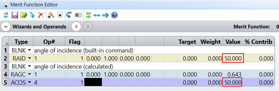
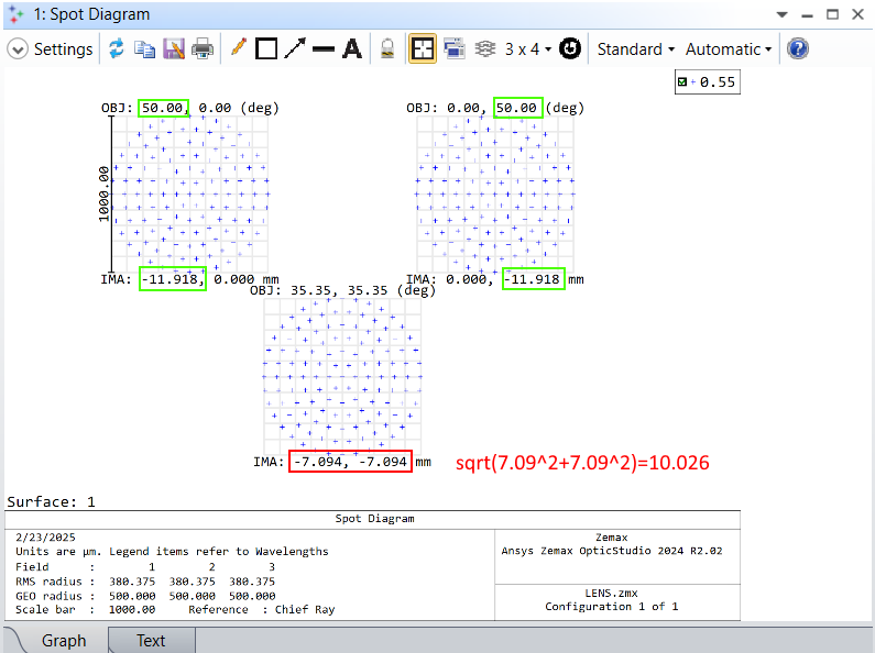
This is the standard spherical coordinate, where we ignore the radial dimension as we only need to describe the angle. It’s not exactly used in any analysis in OpticStudio, but we can still find it somewhere. For example, the RAID is basically the absolute value of θ. The Maximum Field shown in Field Data Editor, when the Field Type is Angle, is also the θ.


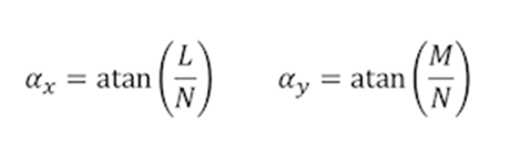
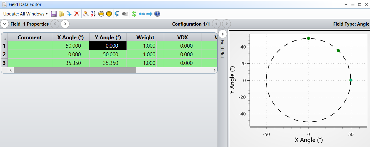
Field Angle in sequential mode (αx, αy)
This is mainly used in Field Data Editor for defining the angle of a field. 

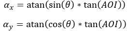
At first, it might look weird , but there are some benefits. For example, imagine we have an object plane at finite space with half width X and Y, and its distance from entrance pupil is Z. If we send a ray from object point (0, Y) to the center of entrance pupil, the ray angle on YZ plane is atan(Y/Z). Similarly, the angle in XZ plane is atan(X/Z) for object point (X,0). Now if we want to define the angle for corner object point (X,Y), the corresponding angle settings is straight forward: (atan(X/Z), atan(Y/Z)). In other words, this angle definition has a good similarity when you want to match your angle definition to an object point, even if the object is virtual and at infinity. It’s often the case, we need to define the field for finite or infinite rectangular object plane and this is where this definition can be useful. Note this coordinate is similar to Cosine Space, that we cannot distinguish directions at -z and +z sides. When the absolute value of αx or αy is larger than 90 degrees, we need to handle it differently. See Help File for more information.


Detector intensity (luminous intensity) view (θx, θy)
The good point of this definition is the distance of any point to the origin on this coordinate is exactly the angle θ. And the rotation angle from +x axis is exactly same as the definition of spherical coordinate ϕ. From this coordinate, it’s easier to imagine the direction at any given point. Note this coordinate is similar to Field Angle or Cosine Space, that we cannot distinguish directions at -z and +z sides.


Theodolite angle (Azimuthal, Elevation)
Note this is different to spherical coordinate. If we only use its “Azimuthal” angle, it’s equivalent to the θ in Spherical coordinate. However, if you further add “Elevation” angle, it’s not equivalent to the ϕ in Spherical coordinate.
The mathematical way to understand how this works in Zemax OpticStudio is described as below.
1.    When both are zero, the direction points to exactly +z.
2.    When one or both are non-zero, we first handle Azimuthal angle and then handle Elevation angle.
  *    First rotate around Y axis by Azimuthal angle. We get new z axis and new x axis.
  *    Second rotate around new X axis by negative Elevation angle.
3.    The above method is called intrinsic rotation because we use the new axis. It’s equivalent to extrinsic rotation with inversed order, as below.
  *    First rotate around X axis by Azimuthal angle. We get new z axis and new x axis but don’t use them.
  *    Second rotate around old Y axis by Elevation angle. 
In contrast, in the same, the spherical coordinate can be considered as one of the following rotation
1.    Extrinsic rotation: X (theta), Z (phi)
2.    Intrinsic rotation: Z (phi), X (theta)
 

FAQ about Max Field and Normalized by in Field Data Editor

In Field Data Editor, when the Field Type is Angle, we show Max Field and Normalized by in the dialog as below.

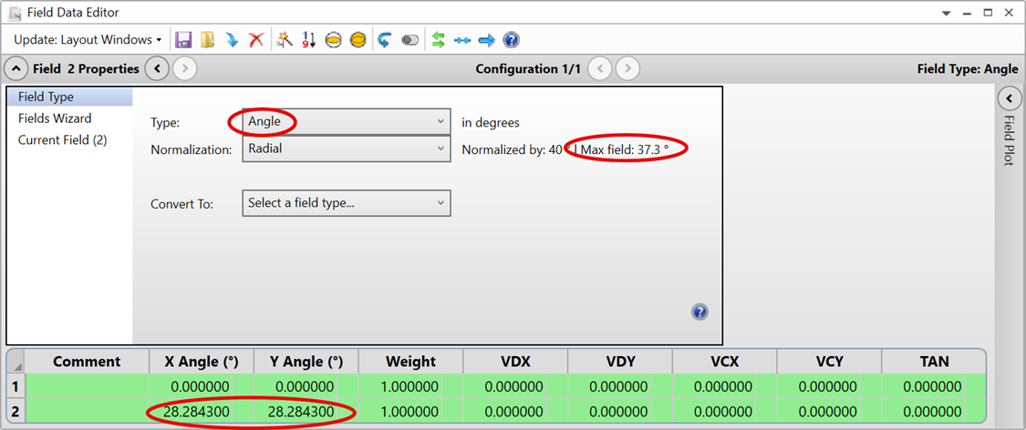
The Normalized by represents the distance of the point to the origin in Field Angle space, which means it’s calculated as sqrt(αx^2 + αy^2), while the Max field is the θ, which is the Spherical coordinate.

Did this topic help you find an answer to your question?

4 replies

MichaelH
Ansys Staff
Forum|alt.badge.img+2
  • Ansys Staff
  • 342 replies
  • February 19, 2025

Hey ​@Michael Cheng , thanks for this great writeup.

There is one more very important consideration for angle definitions in OpticStudio, namely when using Angle as the Field Type definition.  As you mentioned, there is a conversion between the direction cosines L, M, N and the Field Data Editor’s X Angle & Y Angle, namely:

This is a slightly simplistic conversion and only works when either L or M is 0 (the field point falls along one of the axes).  I’m going to call this case the “ground truth”.  If we measure the angle of incidence the ground truth makes with the paraxial Entrance Pupil (Object plane is not tilted), we get the following equation:

AOI=acos⁡(N)=α

So, if we write (0, 50) for the X/Y Angle, then the angle of incidence on the Entrance Pupil will be 50deg.  

However, if we keep the normalized field the same and we rotate the field to be along one of the diagonals such that the new coordinate is (35.35, 35.35), then the angle of incidence becomes 45.1deg (note that by selecting Rectangular Normalization in the FDE, we can decouple the Hx & Hy normalization and use Hx=Hy=1 to represent the diagonal)

If we plot both of these fields in the FDE, we can see that the normalized field coordinates are the same but the AOI is different:

So, it’s only the ground truth that accurately reflects the Field Data Editor value as the desired Angle of Incidence, even when the normalized field coordinate is preserved.  I believe that most users expect to have the same angle of incidence (same “cone” of light) regardless of the rotation of the field, so an extra conversion is needed.

This issue arises due to compound angles and decomposing our alpha angles from the FDE to direction cosines.  Simply taking the arctan of the direction cosines will only provide the angle as projected on the X & Y axis.  To get the true starting field angles which will provide a constant angle of incidence, you need to account for the field rotation angle:

Where θ is the clockwise rotation of the field from the +y axis, AOI is the ground truth angle.  The diagram below illustrates the X/Y projected angle as well as the rotated angle which provides a constant AOI:

This will produce a “distorted” normalized field coordinate circle but it ensures that every blue point below will map to a constant angle of incidence on the Entrance Pupil.  This becomes extremely important for a lot of custom analysis and Monte Carlo post processing where you’re trying to accurately capture off-axis field points.


Michael Cheng
Zemax Staff
Forum|alt.badge.img+2
  • Author
  • Zemax Staff
  • 142 replies
  • February 20, 2025

Hi ​@MichaelH,

Thank you for much more details. It’s exactly one important point I was trying to explain, while probably I didn’t explain well. I think your explanation will help to more people.

Just for providing different viewpoint, which I think it’s same as you explained, I rather would think it’s mainly two different coordinate systems: (αx, αy) vs. (theta, phi), where cos(theta) = α as you described. Intuitively, we may think αx^2+αy^2=theta^2, however, it’s not true because they are different coordinate system.

I don’t know the initial reason why we choose (αx, αy) for Field Angle, but I can see it has a benefit. Here is an example (well just repeating what I shared above):

  1. Assuming we have an rectangular object plane with side of 23.8 * 23.8
  2. Now we have defined two Field Angle for the two points (-23.8, 0) and (0, -23.8) on the object plane, which are the maximum value on X and Y axes. Let’s say the corresponding Field Angle is (50, 0) and (0, 50) as shown below.
  3. Now if I want to define a new field for the object plane point (-23.8, -23.8), I can simply set up (50, 50) Field Angle and it exactly give the ray that comes from (-23.8, -23.8).

This coordinate system gives you an easy way to set up when you consider in a rectangular object plane.


This will be true even when the αx=/=αy.


MichaelH
Ansys Staff
Forum|alt.badge.img+2
  • Ansys Staff
  • 342 replies
  • February 24, 2025

Hey Michael,

Thanks for the clarification.  What I’m talking about is slightly different.  When OpticStudio initially maps a normalized field coordinate (regardless of what the X & Y coordinates are), you will get a different (x, y) value on the image plane if you have a different clocking angle about the Y axis in the Field Data Editor.  This is due to a difference in projecting angular space onto a 2D object plane and the current mapping for alpha angles to direction cosines.  

In the first picture you have above, there are 3 fields:

  1. (50, 0)
  2. (0, 50)
  3. (50, 50)

The first 2 fields have the same normalized radius of 50, but the last field has a normalized radius of 70.17.  If you change the last field to a coordinate of (35.35, 35.35), you will have all 3 fields laying on the same normalized circle:

For a rotationally symmetric system, all three of these fields should produce the same radial coordinate on Surface 1 (or the same Angle of Incidence on the Entrance Pupil).  If you look at the radial coordinate on Surface 1 from the Spot Diagram, you can see that Field 1 and Field 2 (which both lie on one of the axes such that either L or M is 0), the radial coordinate is 11.918mm.  However, if you look at the radial coordinate for Field 3 (which has the same normalized field angle of 50deg), you get a radial coordinate of 10.026mm.

The concept with radial symmetry is you should be able to choose any clocking angle for the input field and get the same output.  However, the way OpticStudio converts from alpha angle to direction cosine means that you have a periodic symmetry that only matches with reflections about either the axes or the diagonals.

When converting from angular space to linear space (lens units), there will be an inherent mis-mapping of values.  So, if you keep a perfectly circular set of field coordinates, you will get a distorted set of image coordinates (this is the red and blue circles I had at the end of my original post).  In order to get a circular set of image coordinates, you will need to use the equation I mentioned:

This doesn’t affect any individual built-in analysis but it becomes important when you start looking at system level designs where you might have different camera measurement angles for a camera module or if you’re trying to create a custom analysis.  I also think this equation provides more insight to my article from a few years ago about Image Simulation and using Angle vs Object Height:

https://www.linkedin.com/pulse/anamorphic-object-pixels-michael-humphreys


Michael Cheng
Zemax Staff
Forum|alt.badge.img+2
  • Author
  • Zemax Staff
  • 142 replies
  • February 24, 2025

Hi ​@MichaelH,

Thank you for more information. Sorry I think I probably really didn’t explain well, but what you explained is exactly what I wanted to say. Above I mentioned many people would think αx^2+αy^2=theta^2, where the theta is the AOI you mentioned, while this is not true. In other words, in your syntax, αx^2+αy^2 will never be equal to AOI^2.

I think it’s already good enough to show αx^2+αy^2 != AOI^2, but the example you showed with image height explains it better.

The only point I added is I think the way we define the coordinate (αx, αy) actually has a benefit, although it can be confusing when people find αx^2+αy^2 != AOI^2.

I don’t have more to add on top of what you explained. It’s very clear to and I believe this is very useful for users who check this thread. Thank you for patiently adding picture and examples. :)


Cookie policy

We use cookies to enhance and personalize your experience. If you accept you agree to our full cookie policy. Learn more about our cookies.

 
Cookie settings