Hi,
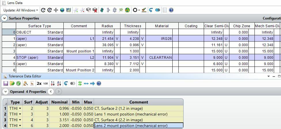
I have a two element design and I am a struggling with understanding how the airgap errors are handled and input in the tolerance data editor (TDE). Below are what I see the airgap errors to be:
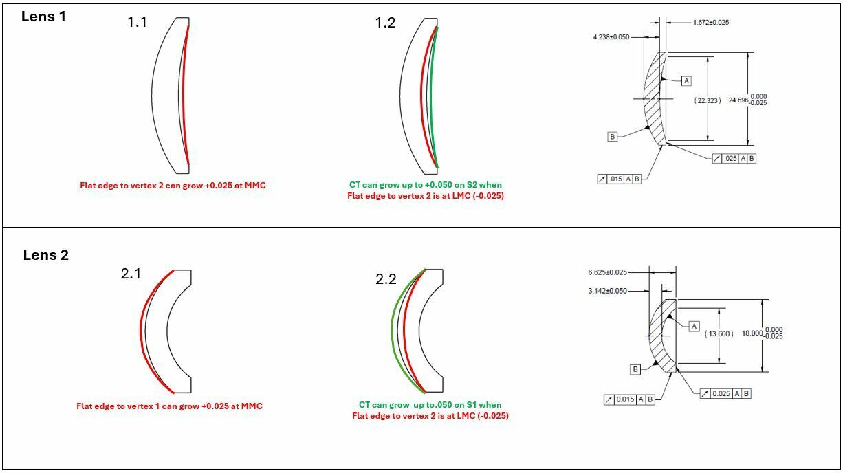
1. Distance tolerance between lens 1 and lens 2 barrel seats
In TDE
2. Thickness tolerance between lens 1 surface 2 vertex and the flat mounting interface (sag of R2)
Set up dummy surface?
3. Thickness tolerance between lens 2 surface 1 vertex and the flat mounting interface (sag of R1)
Set up dummy surface?
4. Center thickness of lens 2
In TDE
5. Center thickness of lens 1
In TDE
For example, my concern is that if I input TTHI CT error for L1 of 0.050 and flat edge to vertex error of .025 Zemax will try to take the cumulative of this, .050 + .025 = .075. Below I show in 1.2 this would not occur as the CT would be out of spec.