

Hi all,
I hope you are all still well. Apologies for another query on my part!
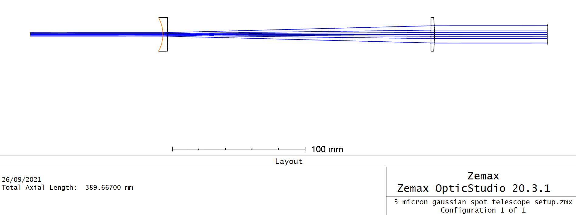
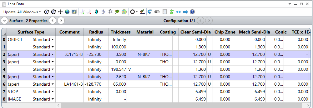
I have been aiming to simulate a system that consists of a 5x Galilean collimating beam expander consisting of a -50mm plano-concave lens (LC1715-B, Thorlabs) and 250 mm plano-convex lens (LA1461-B-ML, Thorlabs), prior to a 25.4 mm plano-convex focussing lens (LA1951-B, Thorlabs).
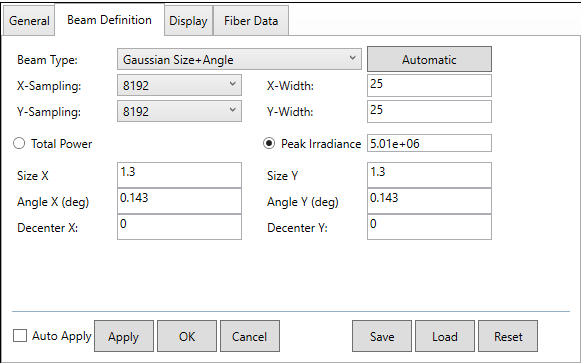
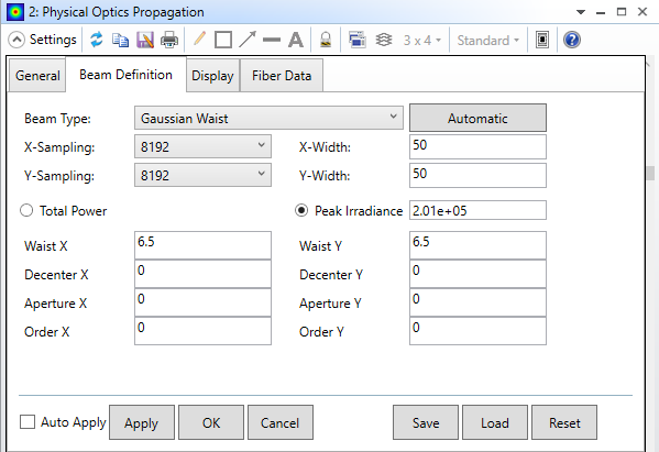
The beam input to the beam expander is defined as having a 1/e^2 diameter of 2.6 mm, with a peak irradiance of 5.01 x 10^6 W/mm^2 and a divergence of 0.143 degrees (derived from an M^2 of 1.3). This theoretically gives an input beam of 13 mm 1/e^2 diameter into the 25.4 mm focusing lens, with this producing a focussed spot size of 3 micron (albeit with considerable spherical aberration). I wish to plot the axial peak intensity distribution of this rapidly diverging Gaussian spot using POP.
I have been able to successfully collimate the beam expander setup using the REAY AND RAED operands within the Merit Function Editor. I did this in a separate .ZMX file to avoid potential sampling issues, with it being a relatviely long propagation distance and tight focus. This provided the expected beam output of ~ 13 mm 1/e^2 diameter. It has a peak irradiance of around 2x10^5 W/mm^2.
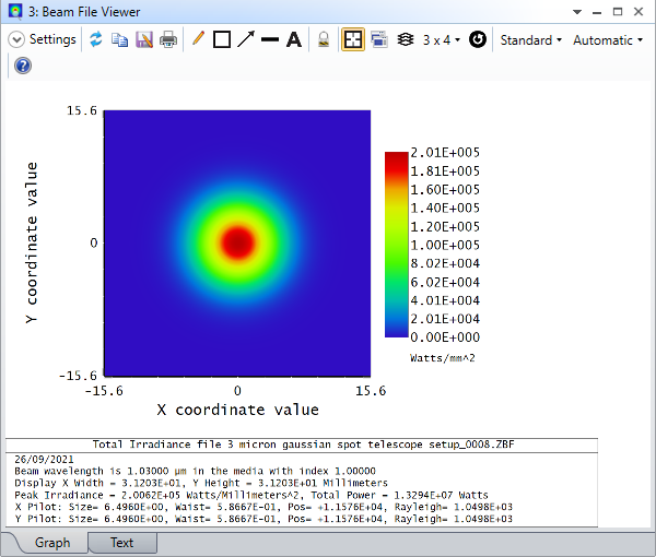
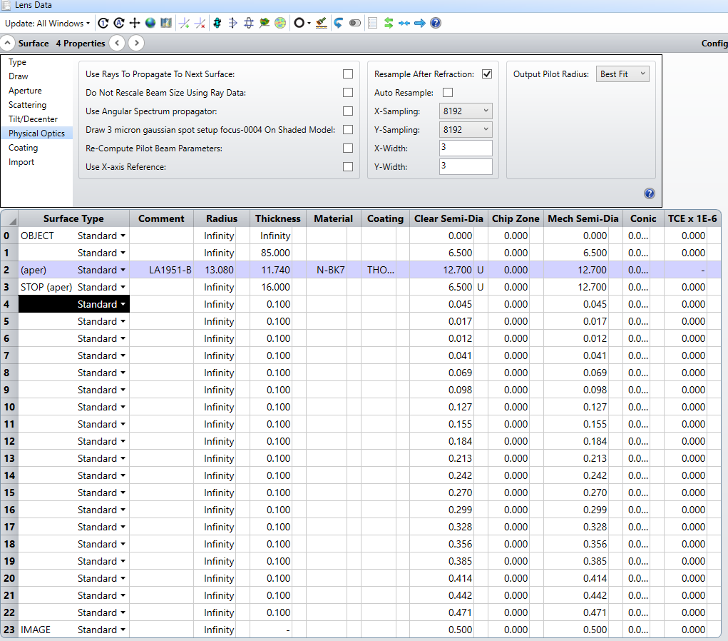
Using this beam diameter and peak irradiance for the input beam definition in the separate focusing lens .ZMX file, I have been able to resolve the expected beam shape of the tightly focussed 3 micron Gaussian spot with surrounding rings (from the spherical aberration).
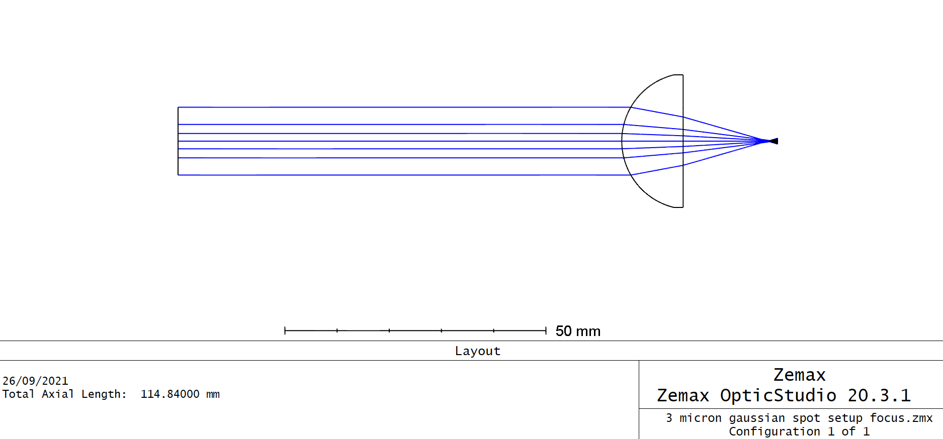
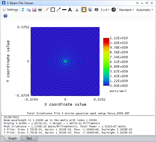
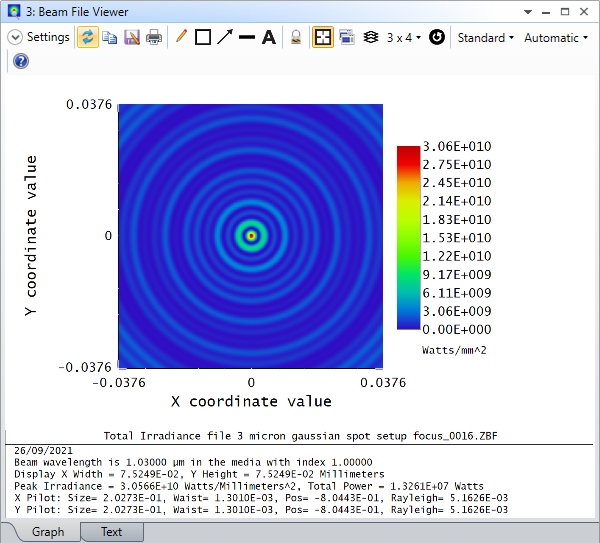
However, the beam is not highly divergent as I would expect, instead maintaining its 3 micron diameter across an axial range of over 1 mm? I recall previously being told that if the spherical aberration is visible on the layout plot (which it is here) that you should use ray tracing, but I am unsure how to (or if it is possible to) extract peak irradiance information using this simulation method?
I have attached the .ZMX and .ZOS files for the focusing lens setups for reference.
Thanks for any help you can provide!