Comparison of custom dll surface and CAD lens

  • 17 June 2021
  • 3 replies
  • 158 views

Hi all! 


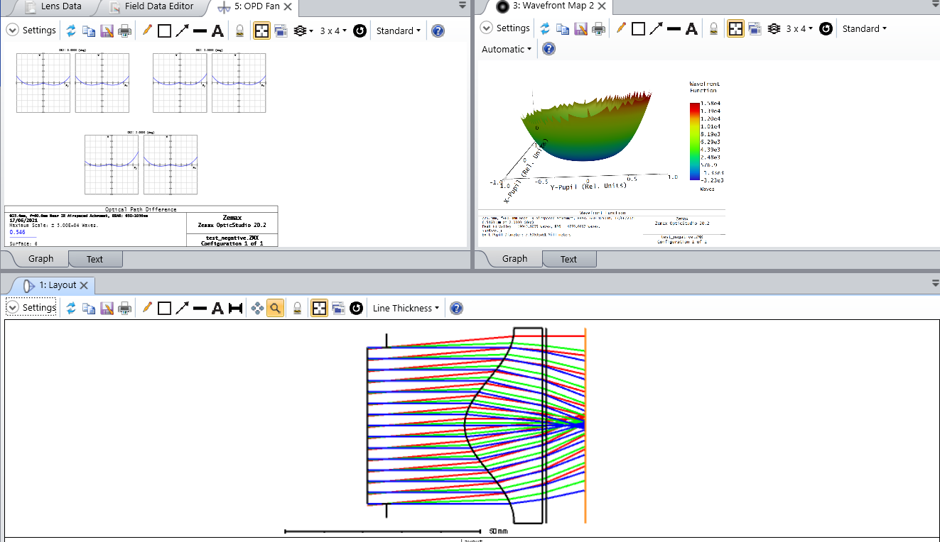
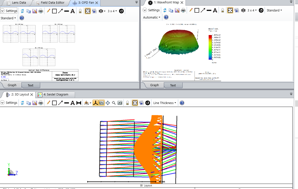
I have done user defined dll surface and want to check its accuracy. For this, I did a lens with such surface on one side and plane on the other in SolidWorks and opened it like .STEP file as a non-sequential component. In the second Zemax file, I opened my user-defined dll. All dimensions, apertures the same. Also, I can see that rays go through the lens in almost the same way. Spot diagrams look very similar. But I want to compare the wavefront map and here I have a huge difference also ray fan very different and I cant understand the reason. It's my first time with non-sequential mode, maybe someone can help me with good advice? Thank you a lot 

dll.pngsolid.png

3 replies

Userlevel 7
Badge +2

Hi Marta,


I agree with Andrew. In addition, if I understood correctly, you are comparing your DLL, with a non-sequential STEP file. In this case, you might also want to check the Chord Tolerance, and Maximum edge length in the CAD tab of the non-sequential STEP properties. Those parameters determine the accuracy at which your STEP is rendered in OpticStudio, but it is also used as a starting point to determine the real ray intercept with the surface of this object. I'm not certain it will apply to your surface, but it can give slightly different results depending on the geometry of the object.


Lastly, you could also try to export the surface sag of your DLL, try to fit it with your surface model (with Python or MATLAB), and measure the RMSE for example.


I hope this helps.


Take care,


David

Userlevel 2
Badge

I would carry out a ray trace on a single ray at an off axis point around the steepest gradient of the lens.  Then check in Zemax the x,y,z points of intersection of the ray and the surface normal l,m,n vector at the intersection point to at least 6 digits of accuracy and compare this with the same calculation done in SolidWorks.  Having written dll's for Zemax surfaces before I have found that it is easy to make a mistake in surfaces with lots of aspheric parameters particularly when your dll is calculating the normal direction.  If there is a mistake in your surface normal calculation these can be difficult to spot.


Andrew

Thank you both, it's very helpful, now I have received some different results. My Solid body (.STEP) was built as Matlab surface that fits dll surface. I checked normals by Matlab and in Zemax, corrected some errors and now normals are pretty the same, but still have a problem with the wavefront map, not so significant, but still. And now will search for some information to understand what does mean all parameters for single ray tracing for exit port from non-sequential component, cause Zemax gave me parameters and I cant understand them. Before exit port and after - all clear. Thank you a lot one more time  

Reply