Solved

Using user-defined variable parameters in the optimization process Dynamic CAD link model

  • 26 August 2021
  • 3 replies
  • 397 views

Hello, Zemax community!

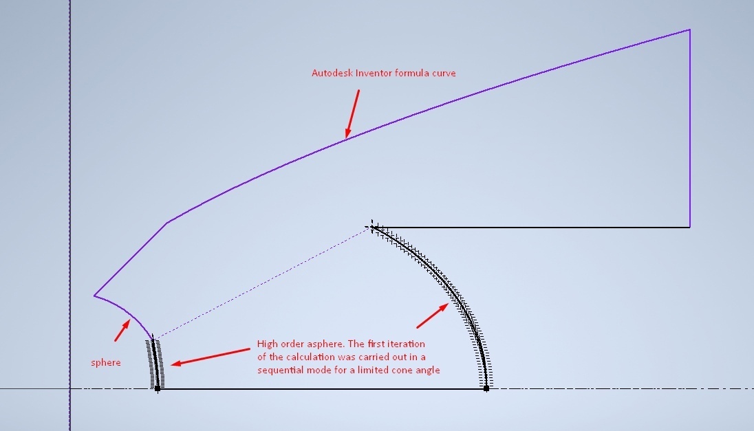
I am interested in optimizing an optical system with an imported CAD model (collimator). Zemax knowledgebase has an excellent article explaining how to use dynamic model links ("Using the OpticStudio Dynamic CAD link"). However, only model parameters that are explicitly used in the model can be used in optimization. This slows down optimization when it comes to optimizing a surface profile that can be plotted using a few dozen points rather than a few polynomial coefficients. This is inconvenient when it comes to optimizing the surface profile, which can be constructed using several tens of points or several polynomial coefficients. Unfortunately, the curve equation coefficients specified by the user in the CAD program are not displayed in OpticStudio. Is there any way to use user-defined parameters of the CAD model in the optimization process in OpticStudio?

icon

Best answer by Flurin Herren 24 January 2022, 14:22

View original

3 replies

Good afternoon! Thank you for your responses.
Speaking in more detail about the idea that I wanted to implement, it was supposed to be a plastic TIR element that works in a non-imaging lighting system. The global goal was to create an optical system with a variable angle of radiation divergence and an approximately uniform distribution of illumination. I was wondering if I could use the input surface, the total internal reflection surface and the output surface as optimization surfaces by defining them in the CAD model as surfaces of revolution, the profile of which is given by the equation. Then the coefficients of the equation could be used as optimization parameters.

The figure shows a sketch of the model, the optimization of which I planned to carry out. This is not a working option because the sketch curves are fixed. It was assumed that the near axial part is calculated in sequential mode and defined in CAD as well as the TIR surface using the surface equation. I think I wanted a too simple solution, since I thought about such a trivial solution as optimizing a single CAD model.
At the moment, there is an understanding that perhaps a combination of inconsistent "Even Asphere", "Standard lens" and "Freeform Z" surfaces can serve as a solution in such a way that each surface will roughly recreate a part of the CAD component.
I'm still learning the program and I like that there are different ways to solve problems.

Badge +3

Hi Devorse,

Thanks a lot for that interesting input!

As Sandrine already mentioned correctly: (Only) Dimension values associated with the part can be defined as optimization variables, may be placed under multi-configuration control, and can be perturbed or used as compensators during tolerance analysis, just like any other parameter of a built-in OpticStudio object. The position and tilt of the part may also be optimized and toleranced in the usual manner.

That said, you might indeed be better off if you are trying to model the part with a native OS tool. Within the Help Files (Directory given below) you can find a list of native Non-sequential Geometry Objects

And the documentation of the Freeform Z Object can be found here:

Feel free to elaborate your specific case a bit further here and I am more than happy to assist you along the way

Userlevel 6
Badge +2

Hi Devorse,

I had a quick chat with one of my colleagues and we think it is a limitation of the CAD link. That being said, my colleague will check next week as he is our CAD expert.

I was wondering if you could define your CAD part with an OpticStudio built-in model instead. For example we have the Freeform object where you define a profile (sag points) along YZ and then the software does a rotation. 

Would you have a couple of screenshots to share to give us some more information? Thank you.

Reply