Question

Use of PERTURB command in Tolerance Scripts for Thickness

  • 10 February 2024
  • 2 replies
  • 91 views

While populating the Tolerance Data Editor (TDE), the editor automatically generates and also allows the user to specify/modify the Adjuster with a specified column. But in tolerance scripting using PERTURB command, there seems to be no way to specify the Adjuster surface number while specifying the tolerance on a surface thickness . Is this a limitation of PERTURB command for scripting the thickness parameter or that Zemax automatically assigns an adjuster surface leaving no chance for the user to select another surface thickness? 

Any help greatly appreciated. Thanks!

Hi Michael,

Thanks for taking some time to answer my question in such detail. Greatly appreciate it. One thing that I learnt from your suggestion is about ‘Compensator’ solve that I never paid attention to. Seems to be a good tool, but I have yet to use it effectively. 

In fact, I have a closely packed multi-element objective design with some elements double potted on mechanical cells. As a result, some of the spacers between doublet groups compete for Position solve and Compensator solve in tolerance layout. Besides, I have to specify some tolerance on those Compensator as well. So, it is not quite clear yet to me on how best I built by TDE along with LDE solves. On the other hand, the reason I am looking for scripting solution is that I have to PRINT some of my MF operand values as part of Monte Carlo analysis. So, I need a good flexibility on scripting PERTURB command to craft my ZDA file with proper feedback of my tolerance analysis. Ideally, I would have liked Zemax Tolerance Analysis allowing me to use TDE operands along with Scripting as part of with Tolerance Criterion to output of MF operands. To my understanding, this is not possible by Zemax Tolerance Analysis. One can only use either TDE or Scripting, but not both. If I decide to use scripting, I must specify all the tolerances in PERTURB command which I now realize laborious (to manually generate so many PERTURB commands with scrutiny) and is of less potential.

Please correct me if there is anything missing in my understanding. Thanks again for your help.

Regards

Krishna


Hi Krishna,

The Tolerance Script (TSC) is a very low-level tool primarily designed to help automate multi-step tolerancing processes (typically for multi-step optical assemblies).  To my knowledge, the TSC hasn’t been touched/updated in decades, even with the recent enhancements to tolerancing such as Roll operands, off-axis pivot tool, quick sensitivity & tolerance data retention.  

Almost all the effort for tolerancing has been put into the Tolerance Data Editor.  I suspect the TTHI operand originally did not have an Adjust surface so the PERTURB keyword originally did not accept the Adjust column; when the Adjust column was added to the TDE, the PERTURB keyword was not updated.

 There are several areas of the TSC that are more difficult to use than simply using operands + TDE (such as constraining the min/max values for a compensator) and I suspect this shortcoming fails into this category.

Luckily, the Lens Data Editor has 2 solves which you can manually set to simulate the Adjust surface:

  • Compensator Solve (more useful)
  • Position Solve

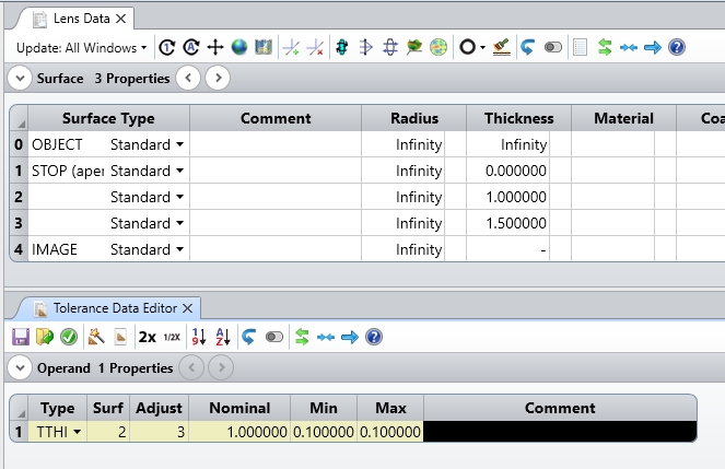
The Compensator solve is more useful because it only considers 2 surfaces while the Position solve could include multiple surfaces.  For example, if I want to adjust Surface 2 and adjust Surface 3, the LDE & TDE might look like:

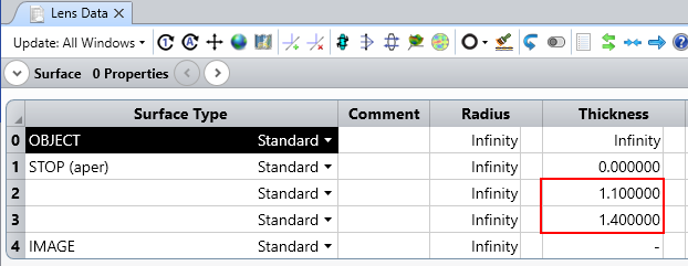
Since both the Min & Max are the same value, I know that every MC file will have a S2 thickness of 1.1 and a S3 thickness of 1.4:

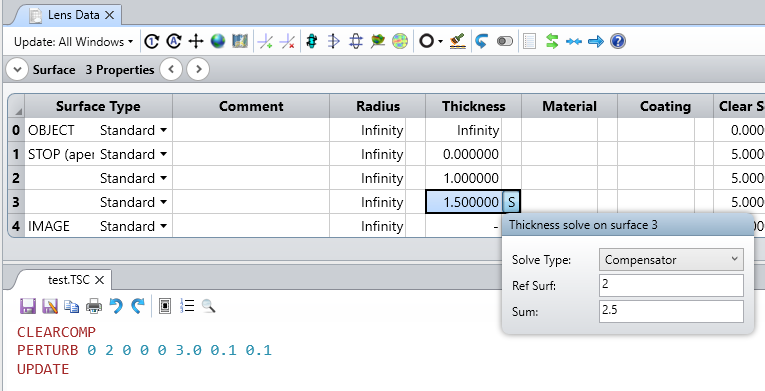
If I want to get the same results from a TSC, then the nominal LDE should have a Compensator solve on S3 (note you need to include the thickness of both S2 + S3 in the solve Sum value):

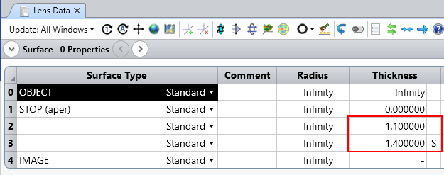
This produces the same result when selecting User Script as the criterion in the Tolerancing window:


Reply