I was wondering whether the tools available within zemax would enable assessing the throughput of an instrument. Specifically, I can estimate the number N of photons gathered in a pixel placed at the FP of an instrument as:
N = R * p**2 * pi * wave * T / (4 * F#**2 * h * c)
where R is the scene radiance, p the pixel size, T the system transmission, h and c are Planck’s constant and speed of light. My assumption is that, at first order, I can simply use WFNO operand value along with the transmission factor from the transmission analysis since the latter takes into account all coatings defined as well as the vignetting defined by any aperture in the model.
Or am I missing something? Thanks in advance for any insights,
Regards
Page 1 / 1
You can’t really equate rays to photons, but I think all you really need is the field-dependent System Transmission. If you have N photons/unit area on the entrance pupil, you need to use the ratio of entrance to exit pupil size, times the system transmission to get the photons/unit area on the exit pupil and then another scaling by area to get photons/unit area on the image plane.
M
For the system transmission, if you’re getting all the values from the Merit Function Editor, you can use CODA to get the system transmission. If you’re using the ZPL or ZOS-API, make sure to use Polarization Ray Tracing.
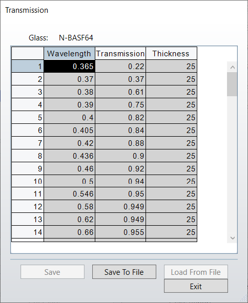
Also, make sure you have coatings on all your Material names in the Lens Data Editor and make sure all the materials you have defined have the proper values for bulk absorption (Libraries > Materials Catalog > Transmission) and they are not just 1.0:
This feels like a problem that would be much easier to solve in a non-sequential fashion. You could define the source geometry, place a dummy surface at the stop and filter by rays that pass through the limiting aperture, and then look at what rays are incident on your detector. That makes the most sense for me since this feels like an Etendue problem.
Sequentially, the issue is that the analyses are somewhat discrete since you have to specify a field. I would consider the IMAE operand as it will consider the coatings (polarization toolbox), and vignetting on surfaces.
You could specify the aperture by NA or cone angle and enable ray tracing so it will angle the cones or rays from the object correctly towards the stop. IMAE will consider vignetting and coatings. You could sample over the fields and get an approximate measure of the Etendue.
Thanks all for your inpupt and insights. I also realize the question is rather braod so I’m going to narrow the scope as I believe you suggest similar approach.
The instrument I’m considering is fully reflective, and I put customized coatings on every surfaces (considering polarization aspects too). What I’m currently doing to consider the field/spectral/input (linear) polarization state variation of transmission is, through Zosapi loop calls, to set the Jones vector components, get the tranmission analysis when varying the Jones input parameter and fitting the Malus law over it enabling me to get the polarization sensitivity and average transmission of the system over the pupil at a specific field and wavelength (doing interpolation to estimate the value at intermediate positions).
About the aperture specification, I input the aperture NA in the zemax file. Obviously if I have an aperture stop, I can continue increasing the NA and what I will see is that the average transmission will decrease (because the rays are vignetted, which is accounted for by the transmission analysis tool). But the decrease in transmission does not follow exactly the same trend as the WFNO decrease when the input NA is going up. It is indeed an Etendue problem and I guess my question is whether Zemax does this type of computation as I’m not able to find the answer in the Help file.