Hello,


I am using the POP Analysis and played around with the 'Beam Definition' parameters. I was a little bit confused, when changing the X- and Y-Width. The Documentation says 'X- Y- Width The initial width in lens units of the region represented by the array. See Auto below.'.


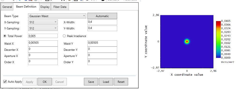
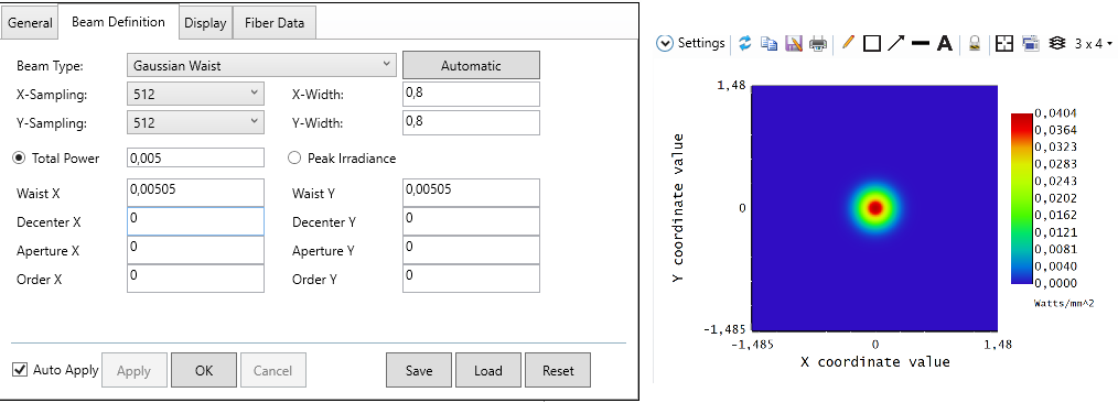
However, the beam appears smaller when I decrease the values for X- and Y-Width. Since the size of the image (defined by X- and Y-Width) is in lens units and the beam size is not changing, the beam diameter should appear smaller on the graph, when increasing the X- and Y-Width parameters.


Here with X- and Y-Width = 0,4mm:


Here with X- and Y-Width = 0,8mm:


Can someone please explain me this behaviour?


Hi Nils,


Thank you for your post!


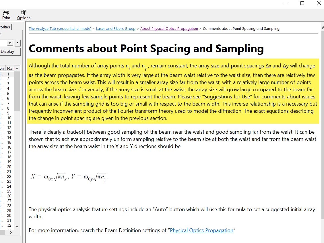
The X and Y width only specifies the array size of the initial beam when it's first being launched. The array size does change duing the beam propagation, expecially when you propagate from inside the Rayleigh range to outside the Rayleigh range. You can find this explained in the Help File at The Analyze Tab (sequential ui mode) > Laser and Fibers Group > About Physical Optics Propagation > Comments about Point Spacing and Sampling


As you can see at the image surface, the array size is not the same as what you specified under the X and Y width for the initial beam, because POP automatically adjusts the array size to accomodate the beam size change during propagation. If you want to know the final beam array size on the image surface, you can find that information in the POP/Propagation Report window.


Let us know if you have any other questions.


Best regards,


Hui


Hi Nils,


Hui gives a good answer above.


One thing you can do additionally is to resample the beam and/or recompute pilot beam parameters at different surfaces. In the properties for each surface is a section for Physical Optics, and you have various options for how to treat POP at that surface. The many options are too long to discuss in a forum, and I would suggest going to the KnowledgeBase articles about POP for more details on the math and physics, but essentially the answer to your question is that POP is re-computing field sizes as it goes along according to the model used, and you can modify these directly with your choices on the beam and the surfaces.


Hello,


thanks for your detailed answer. It is still very useful. I will have a look at the POP articles of the knowledgebase.


Hello,


I have one more question about this topic. 


I want to dynamically move the area I am analyzing in the POP window (from Matlab). However, it is important for my application that the resolution in the POP window is always best possible. 


Unfortunately, I have found that depending on the position of my surface, the grid in the POP window is also resampled.


Is there a way to achieve the best possible resolultion for arbitrary poses of the respected surface?


Reply