Hello Zemax community,


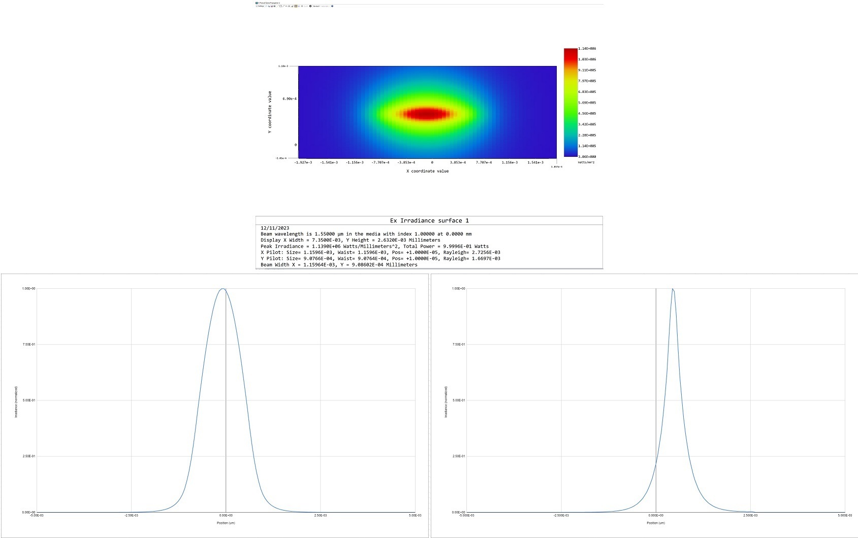
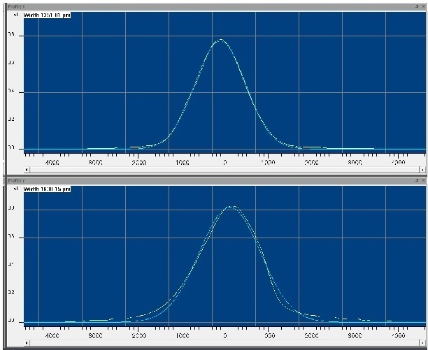
I have a source (ZBF) file which is Gaussian-like in one axis and Lorentzian-like in the other. In addition to the ZBF file, I also have the x and y cross-section far-field angular distribution of power (something like a representative goniometric scan in both axes).


Source near-field:
 

Source far-field:
I am re-imaging the source through an optimized lens pair, with the goal of understanding the resulting image plane characteristics - primarily understanding if/how diffraction effects through the lens pair might result in an enlarged / rounded spot. Initially, I thought POP would be suitable, but the NA of the source seems to be too large, so I am looking for another way to accurately characterize the resulting image.


Looking for some advice on a good alternative approach.


- Partially coherent image analysis starting with the ZBF as object?


- Ray optics / Huygens PSF? Is there a way to mimic the Lorentzian-like profile in one axis only for the apodization factor?


Appreciate any thoughts / feedback. Thank you in advance!


Andrei

@Andrei.Kazmierski 

I like the Partially Coherent Image Analysis (PCIA) approach, using it to model coherent imaging with your ZBF file.  It’s a small object field, which is good for PCIA.  This approach essentially calculates the convolution of an ideal image (a scaled version of the ZBF amplitude object) with the amplitude PSF of the imaging system, and then displays the resulting intensity image.  

Regards,

Jeff


Hello @Jeff.Wilde  - thanks! The PCIA approach seems to be working for me. I have one other question I hope you don’t mind answering: For my initial design, I have a 1x magnification lens pair. My source (ZBF) file is 15x15um, so I have chosen the PCIA file size parameter to be 0.015. If I re-design for >1x magnification with the lens pair, should file size scale accordingly? (this seems to make sense in the image I see - ie, when I increase to 4x magnification, scaling file size to 0.060 gives me the image I expect)


Regards,

Andrei


Hi Andrei,

Yes, for a square object file in PCIA, the “file size” should correspond to the size of this object file as it appears in image space, which is just the object size multiplied by the magnification. 

For a rectangular object file, the “file size” should be the largest linear dimension of the object file scaled by the magnification.

Regards,

Jeff


Thanks again @Jeff.Wilde  - it worked out very nicely.


Regards,

Andrei


Hello Jeff - Hoping you might see this thread and comment:


I am doing some additional PCIA analysis of a ZBF source, but this time I have 2 crossed cylindrical lenses (L1, L2) to collimate a beam (which has significantly different NA in fast and slow axes), followed by a single, rotationally symmetric lens (L3) to reimage the source.


I’m using float by stop size to set my (now round) beam diameter in collimated space before L3, but seeing odd image plane results using PCIA (I expect to see a round beam at the image plane, but get something that is elliptical).


Is there any reason PCIA would not work with this non-rotationally symmetric setup using crossed cylindrical lenses? Thank you in advance.


Regards,

Andrei


Hi ​@Andrei.Kazmierski 

PCIA should work, assuming that you have the correct PSF.  If you are using a circularly symmetric beam in the ZBF file, but the PCIA result is an elliptical spot, then it’s likely the case that your PSF is elliptical.  A quick look at the FFT PSF should tell you.  Also, look at the ray trace layouts (YZ and XZ cross sections).  The collimated beam is  probably elliptical simply because by default Zemax will launch rays with a rotationally symmetric NA. 

Assuming that’s the issue, then I suggest you place a circular aperture on your last lens.  The semi-diameter of the aperture should match the smaller of the two collimated beam dimensions.  Doing so should yield a round PSF, which in turn will give you a round PCIA spot.  Note that with the aperture in place, you can use the “Set All Vignetting” factors tool (in the Field Data Editor) to modify the launch rays so that the collimated beam is round and fills the circular aperture without ray clipping.

Hope this helps…

Regards,

Jeff


Hi ​@Jeff.Wilde - Thanks! This is very helpful and I was able to resolve the issue (it was an issue with the vignetting factors).

One other minor question: In the PCIA tool, how is file size defined for systems with different magnifications in the x and y axes? From the help file ("The full width in lens units of the region defined by the file measured in image space.") my understanding would be to scale file size by the x-axis magnification… will Zemax automatically account for the different scaling in the y-axis?

Regards,

Andrei


Reply