Solved

Non-sequential Tolerancing for a collimated output beam

  • 20 March 2024
  • 6 replies
  • 118 views

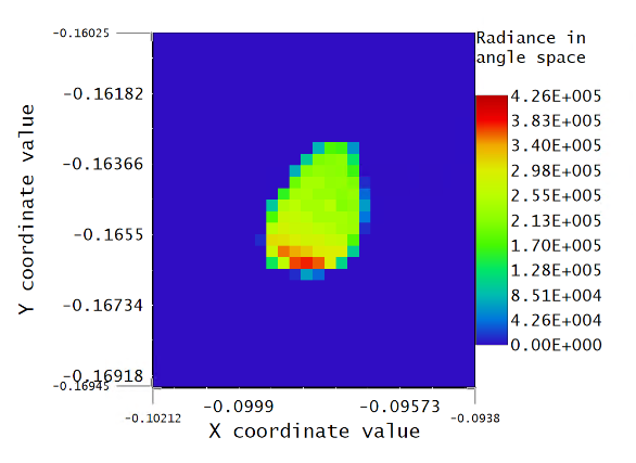
I am trying to perform a tolerancing analysis of a complex illumination system consisting of lots of flat and powered mirrors which expand the output into a large (about 30 cm) output beam. I am trying to establish how many compensators are required in the system to maintain good collimation of the output beam when reasonable manufacturing tolerances are applied. Therefore I am using a merit function which is the RMS angular radius at the output. I want to measure this down to sub-arcsecond levels of precision. However, I am relatively un-interested in the actual direction of the output beam. Applying a set of tolerances to the optical components in my system cause the output beam direction to drift a lot relative to the change in the collimation of the beam and so in order to measure the beam I must use a detector rectangle with fairly broad range of angles (in this case I am using +/-0.3 degrees). The problem is that even with the maximum number of pixels for the detector rectangle object, the resolution is too low to properly resolve the collimation in most cases.

Is there a way to achieve high resolution for sampling the collimated beam, while also being able to detect the beam over a wide range of beam angles? 

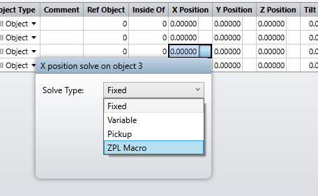
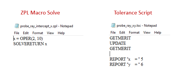
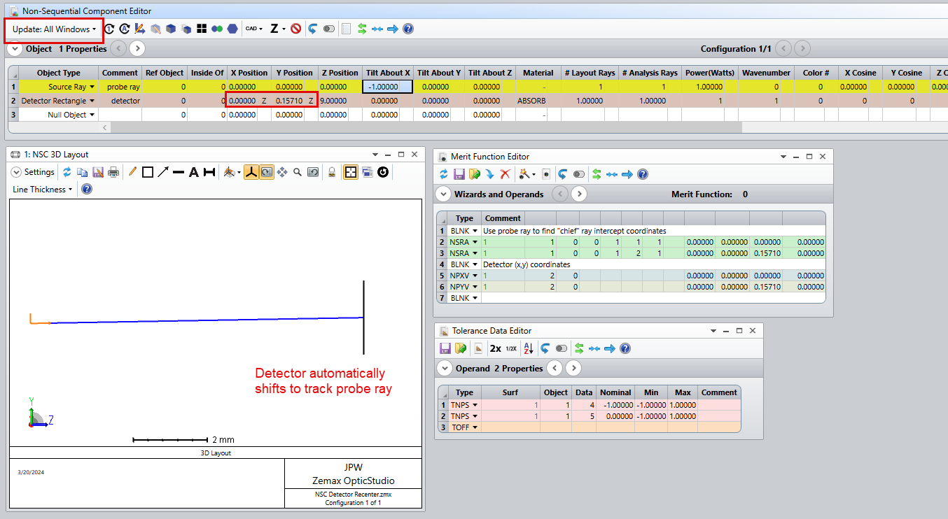
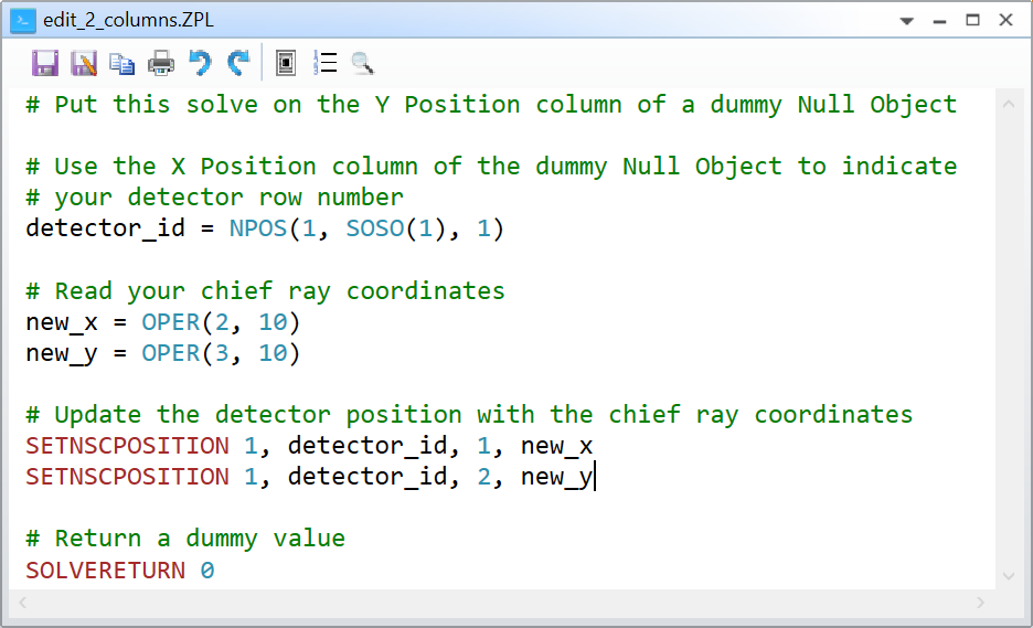
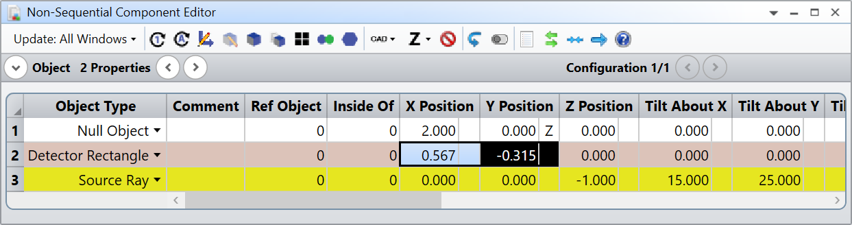
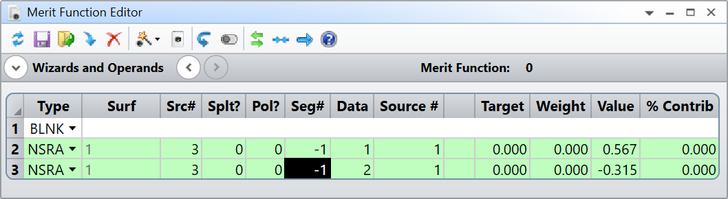
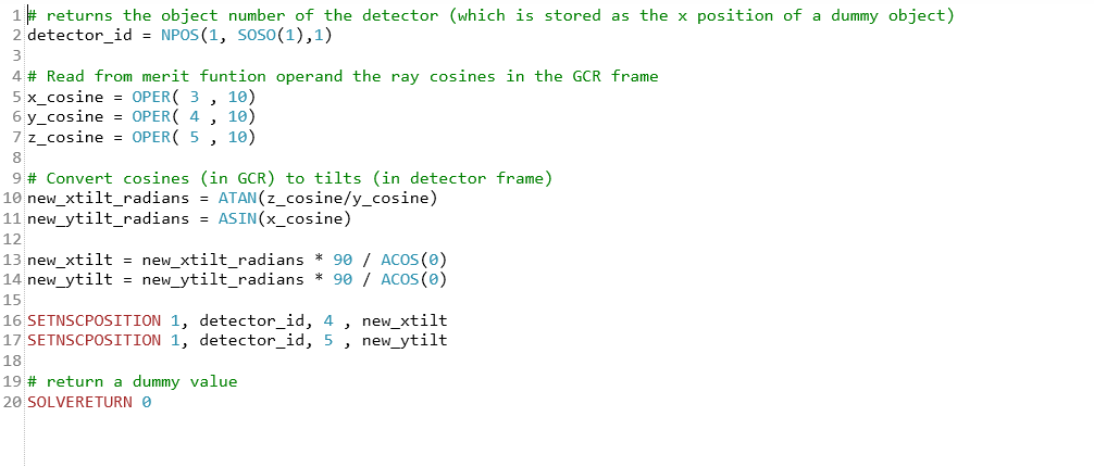
The most simple solution I can think of is to have the detector co-moving with the output beam such that the chief ray hits the centre of the detector. Is there a way to implement this in NSC mode?


An example of the angular size of the beam at the output for the worst case of a Monte-Carlo simulation. In this case the particularly poor alignment means the spot is adequately sampled by the detector pixels.


icon

Best answer by Jeff.Wilde 20 March 2024, 22:52

View original

6 replies

Userlevel 7
Badge +2

@JHutchinson 


That’s an interesting problem. Do you have any prior knowledge about where the chief ray intercept could be, based on the tolerances that are applied?

Take care,


David

Hi @David.Nguyen

Thanks for your reply! 

The system uses a confocal pair of slow off-axis parabolic mirrors to expand the beam (with three fold mirrors in between). My assumption is that a big determiner of the output beam direction will be the angular tolerances placed on the final powered mirror. Therefore I have tried using pick-ups to transfer the tilts of this mirror to the detector rectangle in an attempt to bring the beam closer to the detector axis (which would allow me to shrink the angular range). Unfortunately this hasn’t worked very well, I assume because of significant contributions from the tolerances placed on the other components.

What I need is some way to first trace the chief ray, and then position my detector rectangle accordingly, which strikes me as something which would be trivial in sequential Zemax but doesn’t lend itself to NSC at all!

Thanks again for your help!

Jake 


Userlevel 7
Badge +3

@JHutchinson :

You might want to try using a ZPL macro to set the (x,y) location of your detector.


If you define a single Source Ray object, which represents your chief ray (let’s call it the “probe ray”), then you can use the Merit Function Editor to trace this ray and find its (x,y) intercept coordinates on the detector plane.  The ZPL macro solve then simply extracts a coordinate and applies it to the detector location.  So, you need one solve for x and a second solve for y.

The key issue to pay attention to here is the fact that multiple updates (MFE and NCE updates) are needed to make this work.  In the GUI, if you just select the “Update: All Windows” option, then it should work seamlessly.  In other words, if you perturb your system, the merit function should automatically update, which means the probe ray should automatically trace and update the solve values.  Otherwise, manual updates are needed -- the sequence is: (1) perturb the system, (2) update the merit function to get the new probe ray results, (3) update the NCE to apply these results via the ZPL solve, then lastly (4) update the merit function editor again to extract the new detector coordinates.

However, when running a tolerance analysis, you need to use a simple tolerance script to make sure the updating is done properly.  Here are examples of the ZPL macro solve (for the ray x-coordinate intercept) and the tolerance script:

Note the two GETMERIT calls (it’s not clear that the UPDATE command is required, but if not, its presence isn’t problematic).  The corresponding test model that I put together looks like this:


Here, in the Tolerance Data Editor, I simply apply an angular variation to the probe ray.  The detector now shifts in accordance with the probe ray intercept values.  


When I run a Monte Carlo tolerance analysis, the detector (x,y) shift values are reported as called for in the tolerance script:


Hope this helps...

Regards,

Jeff

Userlevel 7
Badge +2

I am not sure if it is computationally faster but you can use a single ZPL macro solve with @Jeff.Wilde’s method. Basically, have the solve on a dummy object and return a dummy value, and use SETNSCPOSITION from within the solve to update your detector position. There might be a greater overhead in using two solves, but then again I’m not super sure about this, @MichaelH would know. Also note, in NSRA, if you use Seg# = -1 you get the last segment of your Source Ray. Since @Jeff.Wilde had a single segment anyway it didn’t matter.

Take care,


David

Hi @David.Nguyen  and @Jeff.Wilde,

Thanks both for your suggestions! 

Following your advice I have implemented a ZPL script which changes the detector angle to keep the incoming beam at normal incidence. I’m still sorting out some bugs, but this should allow me to tolerance with much better resolution at the detectors and with far less computational cost due to being able to use smaller detectors!

 I did have to tweak things a bit from your suggested macros because in my case I am working in angle space with a collimated beam therefore I need to change the detector angle. That said I can imagine a similar situation arising with a detector at a focal plane whereupon changing the angle detector x and y positions  (as you have done) would be required. This is the macro I have used:


Thanks again for your help! 

Jake 

(Comment removed) 

Reply