Solved

Multiple beams simultaneously in sequential mode?

  • 18 October 2022
  • 7 replies
  • 521 views

Hi Zemax community,


I would like to ask whether it is possible to enter multiple beams simultaneously to a system in sequential mode and analyse their combined ray pattern at the same surface.

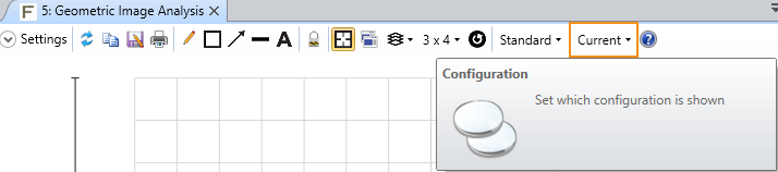
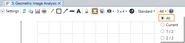
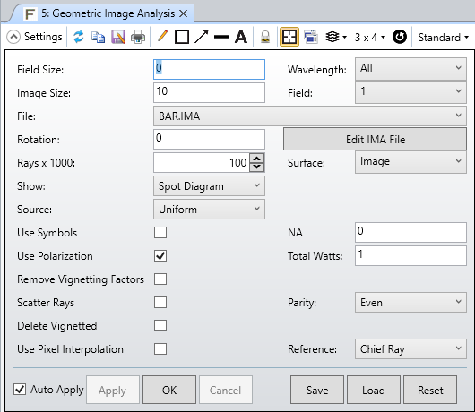
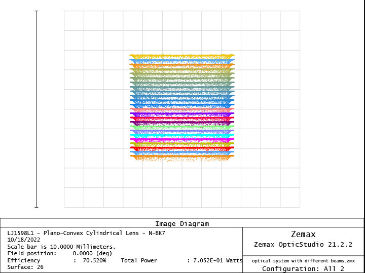
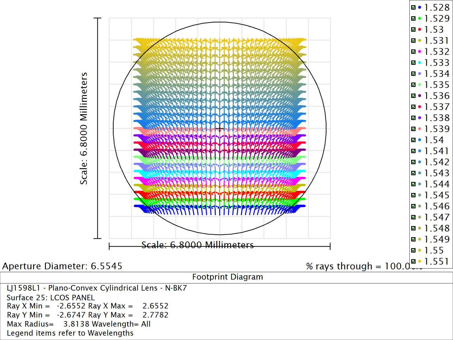
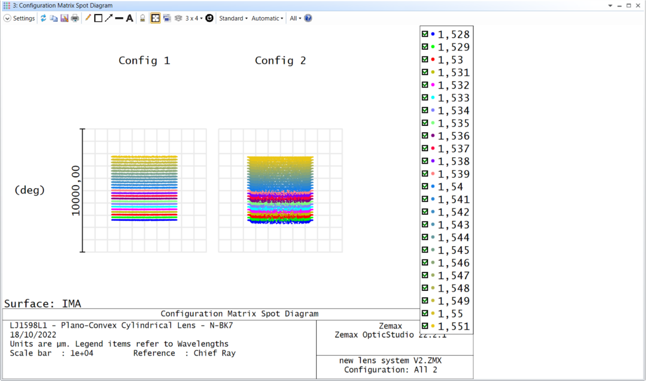
Until now I have experimented with different configurations using the Multi-Configuration Editor, but in the Configuration Matrix Spot Diagram the ray patterns are plotted seperately with a seperate reference. Could the ray patterns be plotted in a combined way (i.e. same diagram and reference) so that the overlap of different beams can be studied?


Spot diagramms with difference reference

A sample file of the optical system is also attached here.


Many thanks in advance,

George

icon

Best answer by MichaelH 25 October 2022, 19:09

View original

7 replies

Userlevel 6
Badge +2

Hi George,

Most analysis are expecting different configurations to represent different static snapshots of a system, not necessarily 2 different inputs to the same system at the same time.  So, most analysis do not allow you to combine different configurations.

However, there are 2 powerful analyses which allow you to combine configurations in one plot:

  • Geometric Image Analysis (for ray-based analysis)
  • Huygens PSF/MTF (for diffraction-based analysis)

To plot all configurations, you will need to change the configuration from Current to All:

To recreate the Spot Diagram, you should set the Field Size to 0 (pinhole source) and set the Show to Spot Diagram:

This then gives the following result:


Hi Michael, thank you very much for your answer. I understood the way the snapshots plot the ray pattern.

Regarding the inputs to the system, is it possible to insert two or more sources simultaneously? For example, two inputs with different input angles. Or each configuration holds its single input with its own properties?


Many thanks,

George

Userlevel 6
Badge +2

Hi George,

Sequential mode tends to work in terms of fields and not sources.  Therefore, the inputs for a Sequential system are defined in the Field Data Editor.  The main thing to keep in mind with fields is the center of all fields (the chief ray) has to go through the center of the Stop (or Entrance Pupil).  So in general, each configuration holds just one “source” in sequential mode.  If you need to define multiple sources, you will need a different configuration for each source and intelligently place the Stop for each source.

You can use the MCE to modify the inputs to simulate different sources.  You will need to use Coordinate Breaks directly after Surf 0 to position the “source”.  The Zemax\Samples\Sequential\Miscellaneous\Bi-ocular lens.zmx file shows one example of how to do this. 

Userlevel 4
Badge

Hi George,

I wonder if what you want is not simply the footprint diagram. It does not work on the image surface but is fine on the previous one (surface 25):


Hi George,

Sequential mode tends to work in terms of fields and not sources.  Therefore, the inputs for a Sequential system are defined in the Field Data Editor.  The main thing to keep in mind with fields is the center of all fields (the chief ray) has to go through the center of the Stop (or Entrance Pupil).  So in general, each configuration holds just one “source” in sequential mode.  If you need to define multiple sources, you will need a different configuration for each source and intelligently place the Stop for each source.

You can use the MCE to modify the inputs to simulate different sources.  You will need to use Coordinate Breaks directly after Surf 0 to position the “source”.  The Zemax\Samples\Sequential\Miscellaneous\Bi-ocular lens.zmx file shows one example of how to do this. 

Hi Michael, many thanks for all the information you provided me with, I saw the example you suggested and helped me understand the concept of the field edittor regarding the sources.

Hi George,

I wonder if what you want is not simply the footprint diagram. It does not work on the image surface but is fine on the previous one (surface 25):


Hi Ray, many thanks for the suggestion, the footprint diagram eventually worked for me. At my first trials in my setup I couldn’t observe any field, but after doing some experimenting with the position and XY widths of the appertures the footprint is now celarly visible!

Reply