Is there any way to setup a tolerance on the m^2 of a beam?
I’m trying to see the effects of variating m^2 on my optical system.
Thanks,
Eli
Best answer by Jeff.Wilde
View original
Is there any way to setup a tolerance on the m^2 of a beam?
I’m trying to see the effects of variating m^2 on my optical system.
Thanks,
Eli
Best answer by Jeff.Wilde
View original
 +4
+4
Eager to see the replies…
I find M-squared generally useful because it helps me understand the quality of a laser. However, I put it in the same category as WFE RMS when it comes to modeling.
What in the world do I use for aberrations / mode profile / … when I have an M-squared requirement? I often look at M-squared from a “supply side” viewpoint - what laser do I buy for this application? Perhaps you are looking at this from a design perspective: how do I design this laser such that it meets an M-square performance requirement?
If your perspective is the latter and you’re designing a system and trying to optimize its M-squared, I would build out optics in my model to evaluate M-squared and use the RMS spot size / POP / PSF / … analyses to evaluate M-squared in the merit function and optimize to that…
-B
Hi Brian and thanks for your input here.
I’m indeed looking from the supply side. Let’s say I assume a source with an M^2 of 1.2 around which I build my system.
I want to know how my system performance will change if it turns out that the M^2 is better/worse than 1.2, and how close to the 1.2 I’d need to be for my system to meet certain (other) criteria.
Thanks again,
Eli
+4
I’ve run into this problem before.
The methods I’ve used are to introduce aberrations in the system with a Phase Surface such that the M-squared > 1.0. I need to add phases that represent the laser physics:
On the supply side of lasers, it is rare to be able to specify the M-squared… you get what you get so you need to see if what you get is good enough for your application. If it is not, then life gets hard because in some cases you may need to homogenize the beam and despeckle the beam.

 +3
+3
Agree (again) with Brian.
M2 and wavefront error are both ‘output’ definitions that don’t help you to create an input. Knowing that an optical system’s wavefront error is flat to a quarter-wave is fine, it tells you the magnitude of the error. But there are an infinite number of wavefronts that have a quarter-wave RMS error...you really need something that gives some kind of frequency spectral response.
For OPD, this might be a set of Zernike coefficients. For POP, it might be a prescription of the input beam as X*TEM00 + Y*TEM01 and Z*TEM10. These definitions would let you define an input beam sir that you could study the response of the system to the input.
 +3
+3
Hi Eli,
Just to expand on the previous comments, if your problem can be handled in POP (i.e., if your system criteria can be evaluated using POP), then I think there is a reasonably straightforward way to obtain the results you may be seeking.
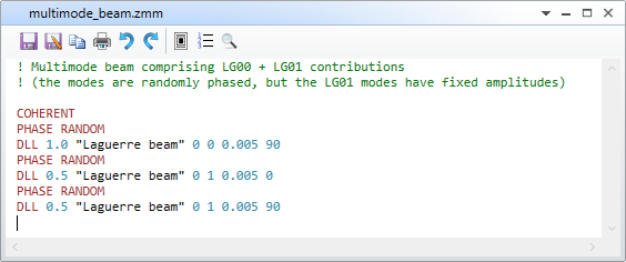
Let’s assume the non-unity M^2 value arises from a laser beam that is slightly multimode. To look at this situation from a statistical perspective, start by defining a beam in POP that is a coherent superposition of a fundamental Gaussian mode plus random contributions from the next higher-order mode (e.g., LG_00 + some amount of LG_01) as shown here:
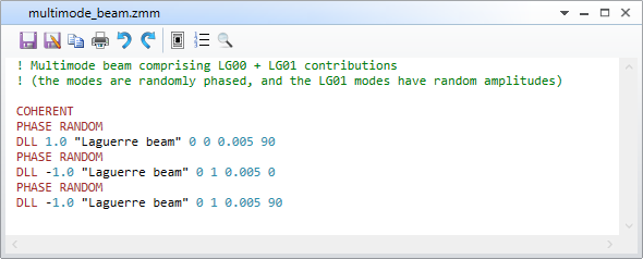
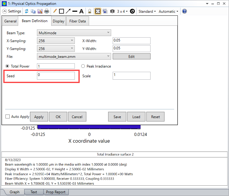
Note the weights for the LG_01 modes are negative, which creates random values (see the help documentation). Now, in POP, set the “Seed” value equal to zero, so that every time POP is updated, it will do so with a different random combination of modes.
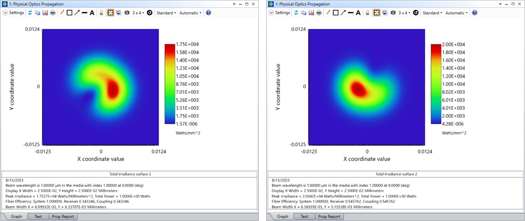
Here are a couple of examples of the generated beams:
Now, let’s assume that we are interested in coupling the beam into a single-mode fiber that supports only the lowest-order LG_00 mode (i.e., this is our system performance criterion).
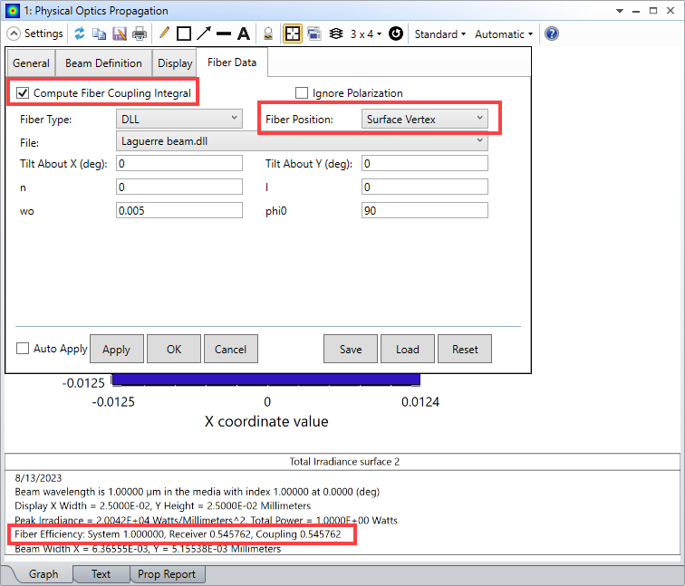
For this demo case, I’m not using any optics (the lens data editor is empty), instead I’m just defining a multimode beam and then seeing how much of it couples into the fundamental mode. However, in general, you would have some optical path with the receiving fiber at the end.
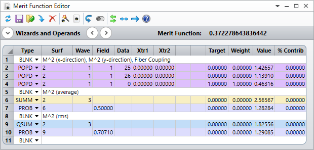
Next, use POPD merit function operands to compute the M^2 values for a given beam (i.e., values of M^2 for x & y directions, along with their average and/or rms values). Also, include the fiber coupling value. There is one very important detail to take into account when using multiple POPD operands if the intention is for all of them to operate on the same beam. As noted in the help documentation:

So, we construct the MF as follows:
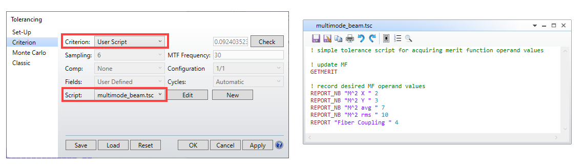
At this point, we can utilize the Monte Carlo tolerancing capability of OpticStudio to generate a random set of beams and record the M^2 and fiber coupling values. To do this, use a simple tolerance user script:
Note the tolerance data editor can remain blank, as the random beam generation is managed by the multimode beam script in POP. You can skip the sensitivity analysis, and conduct only a Monte Carlo run. Here are example M^2 distributions for 2,000 MC iterations, plotted using the histogram feature:
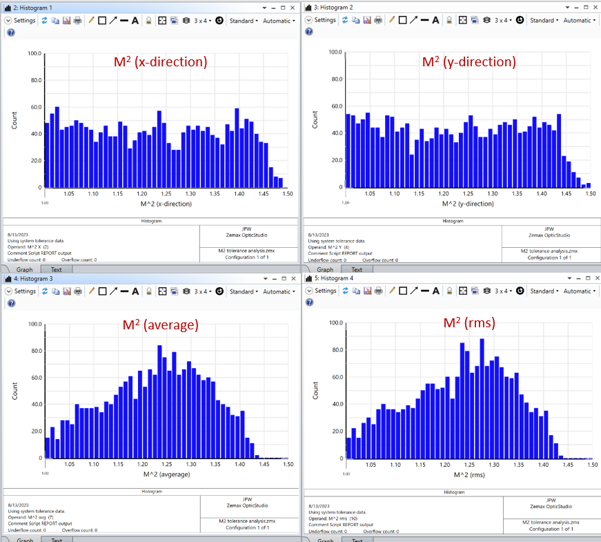
You can see that M^2 spans values from 1.0 to 1.5.
We can also plot the fiber coupling distribution. Moreover, we can easily copy/paste the results into Excel or Matlab and then plot the fiber coupling vs M^2.
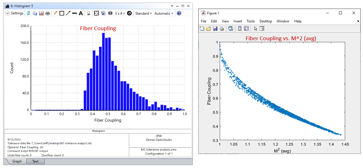
As expected, we see a correlation between M^2 and coupling efficiency. So, we’ve accomplished our goal of seeing how a variation in M^2 affects the system performance metric.
Another interesting test is to change the initial POP beam definition so that constant amounts of the LG_00 and LG_01 modes are always present (i.e., turn off the random amplitudes for the LG_01 modes), but retain the random phasing between the modes, like this:
In this case, you should see the M^2 and fiber coupling values remain essentially constant across the MC samples even though the beam is changing its apparent shape.
Sorry for the long post, but I hope this is of some help.
Regards,
Jeff
+4
-B
+3
Yes indeed. This could easily be edited into a Knowledge Base article.
Yes - thanks a lot
I was hoping to be able to model this with paraxial and not POP - but this is greatly helpful!
Thanks again!!
+3
Thanks for the feedback! OpticStudio is quite flexible, and part of the fun in using it for simulation is figuring out how to leverage this flexibility in an optimal way.
Jeff
Enter your username or e-mail address. We'll send you an e-mail with instructions to reset your password.
Do not provide any information or data that is restricted by applicable law, including by the People’s Republic of China’s Cybersecurity and Data Security Laws ( e.g., Important Data, National Core Data, etc.).
不要提供任何受适用法律,包括中华人民共和国的网络安全和数据安全法限制的信息或数据(如重要数据、国家核心数据等)。