Hello there friends from Zemax,
I am trying to import a freeform surface which I externally generate with some custom numerical routine.
Since I am interested in performing a non-sequential ray tracing analysis of of my system, I export my surface as a CAD object.
I have observed that there are differences in the obtained results depending on which CAD format I use. At the moment I just tested the STL and the STEP fileformats.
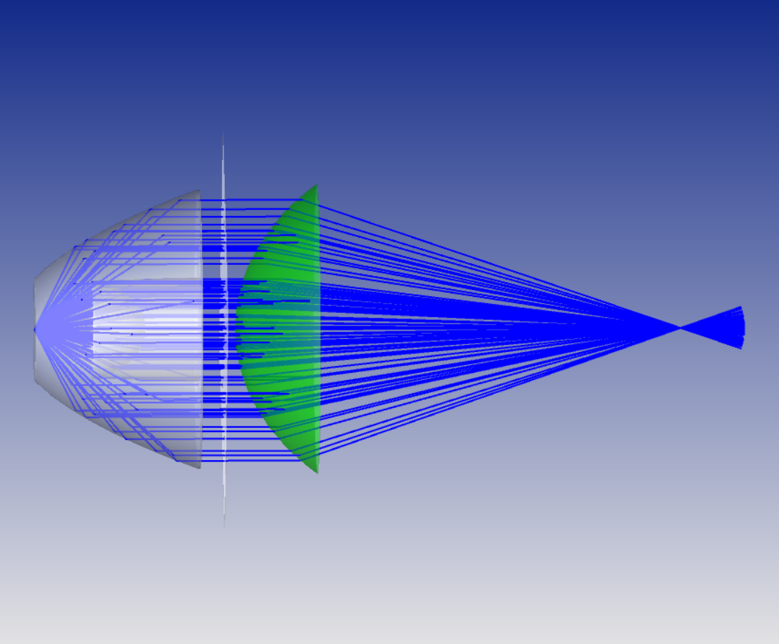
My system looks something like this:

In this case, I have a point source at the origin. The element right on top of the source is a TIR structure. The surface on the right side is just an aspheric surface which I directly transform from the sequential mode into the non-sequential mode. Finally, the rays are focused towards the focal plane in where I have positioned a small detector to evaluate the intensity at the focal plane. In between both lens elements, I have included a rectangle detector to also evaluate the irradiance.
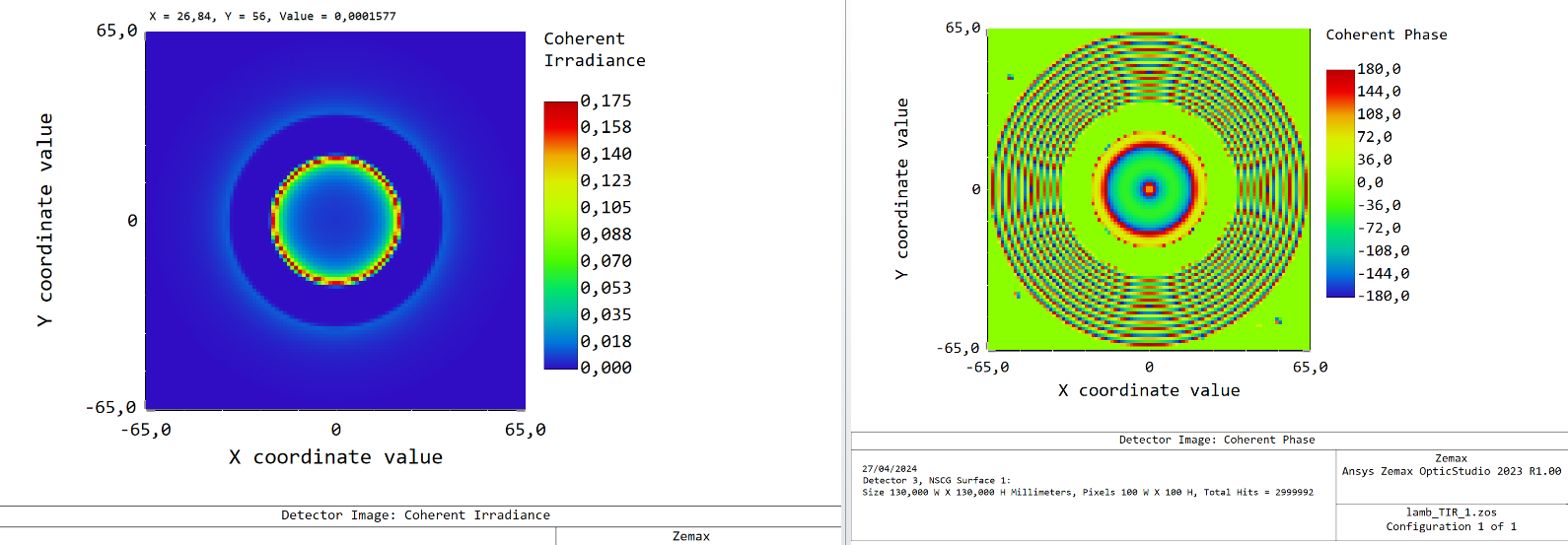
The issue that I am having is related to the results I obtain while extracting the coherent irradiance and coherenet phase for both fileformats that I used for importing the TIR element. (I just show the irradiance for the detector positioned in between both lens elements)
These are the coherent irradiance and phase results for the STEP file case:

And these are the results based on the STL file format:

Clearly, the STL based results cannot really capture the aparent partially coherent nature of the field.
Now, the thing is that for this specific TIR lens I can use the STEP format by first creating a 1D spline and then generating a STEP file from the spline function. However, I have other structures which are not rotationally symmetric and therefore I cannot use the same approach.
Is there any suggestion on what could I do in this case? I am specially interested in evaluated the coherent irradiance because my system is supposed to generate a flat wavefront, so evaluating how well the rays are in phase is important for me.
Any comment or feedback will be appreciated.


