Solved

Detectot polar spike at 0° angle

  • 19 October 2022
  • 4 replies
  • 118 views

Hello everybody,
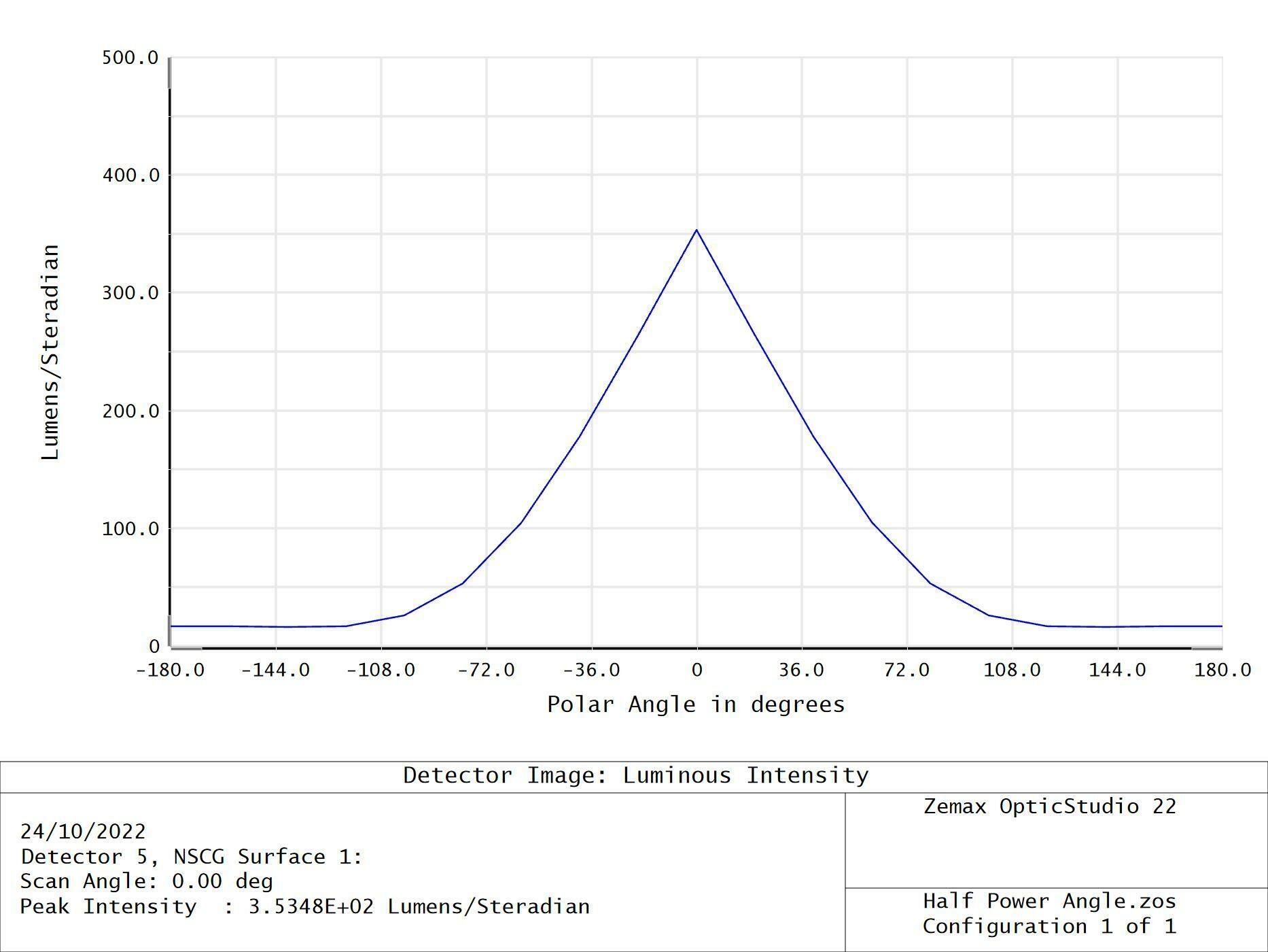
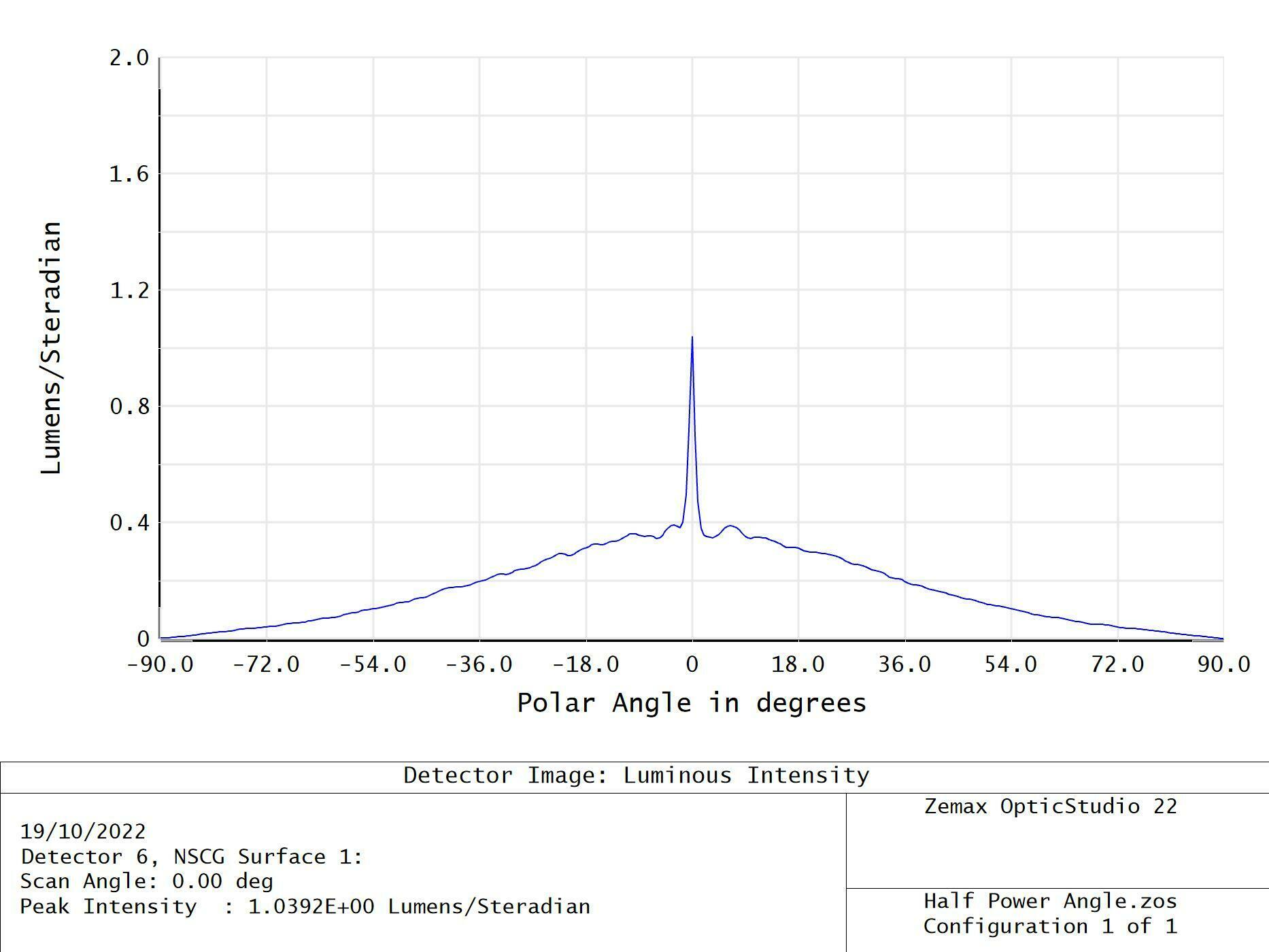
the problem I have has been known to me for some time, but now I am trying to analyze a bulk scatter material. The analysis returns a spike at 0 ° which does not allow me to have a reliable graph. Someone solved the problem with settings or settings.
I have already tried to use a surface detector (but it does not satisfy me) but I would like to use a polar detector anyway.


Thanks a lot.


icon

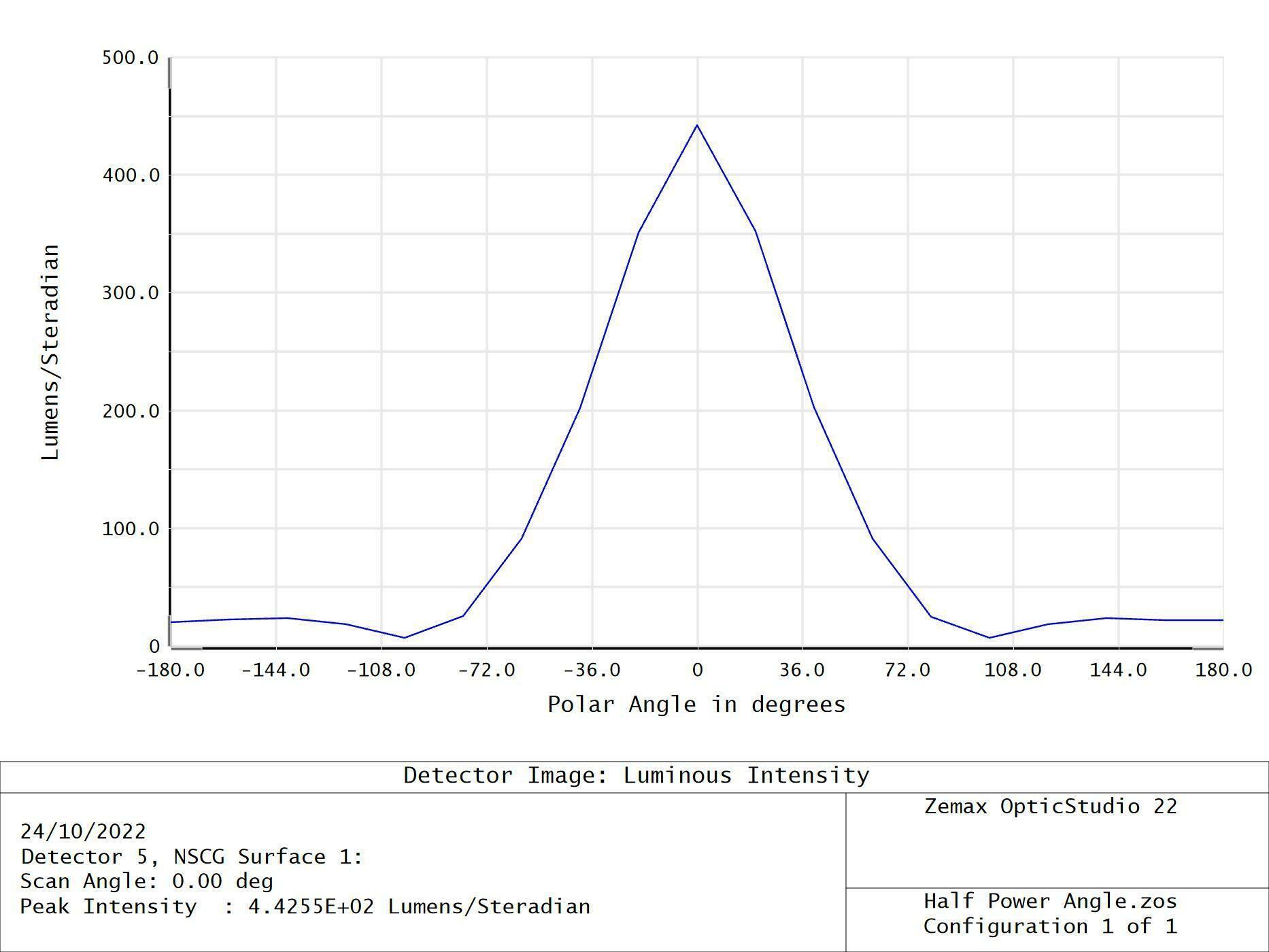
Best answer by Sven.Stöttinger 25 October 2022, 14:40

View original

4 replies

Userlevel 6
Badge +4

Hi Luca,

This has been an issue for years. I have seen both spikes and notches near 0 degrees of polar angle. I suspect that the issue is that due to converging meridians the angular area of pixels becomes very small near the pole, so they are sparsely filled with rays and subject to statistical noise. 

I have found that this can be corrected by either reducing the number of radial and angular pixels in the detector to the minimum required or by using smoothing in the detector viewer to achieve the same result.

Thanks a lot David, I tried to set the radial pixels to 10 and the angular pixels to 12 (the minimum allowed) and to apply a smooth 3 fact, this is the result.


The result without smoothing factor is instead the following.


In the merit function that I am applying, however it is, it reads the non-smoothed values (I think). For completeness I attach the archive file (.zar).
The desire is to find a scatter factor (mean path and angle) that satisfies the requirement of having a certain decay at a certain angle, the problem is precisely the disturbances that distort the reading of the azimuth pixel.


Thanks a lot…..

Userlevel 2
Badge

Hi Luca,

seems to me that your spike originates from rays that are not scattered while traveling through your volume scattering glass. You can avoid the central spike by placing a small “beam dump” to avoid that the 0° angle pass through rays reach the polar detector. Such a beam dump can be a small absorbing rectangle or ellipse located close to the polar detector:


The resulting cross section with standard radial and angular pixel numbers for the polar detector and smoothing factor of 4 looks like this:


You might also save rays as ZRD-files and use the filter function B3 (only showing rays that are scattered via volume scattering on object 3) while reloading the ZRD file into the Detector Viewer  - but this will create quite huge files with larger ray numbers.


Best regards,

Sven


I’ll try it……


Thanks  a lot

Reply