Simulate 2D diffraction grating using customized diffractive DLL
In OpticStudio, currently we only support one dimensional grating. However, it's not difficult to simulate 2D grating. Here we will show an example using diffractive DLL.
You may compile it with the instructions or use the DLL file attached to this article.
Before we start, here are some articles for required background knowledge that we will not repeat in this forum post.
Let's simply open the attached cpp file and observe how it works in non-sequential mode.
This example is mainly modified from the built-in sample \Documents\Zemax\DLL\Diffractive\diff_samp_1.c
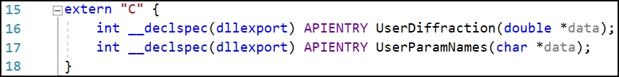
To compile the program as C++ code. We package the functions with extern 'C'.
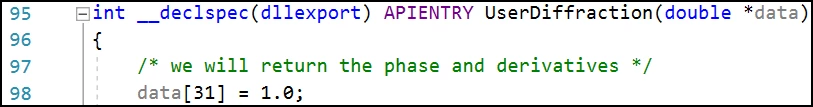
In this example, we only want to return diffraction ray direction and its relative intensity. So setting datai31] = 1 is enough. If we also know the polarization state or the full eletric field value, we can use datau31] = 2.
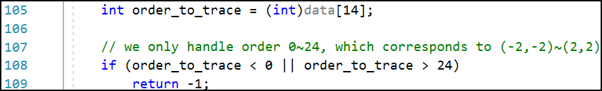
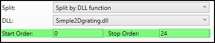
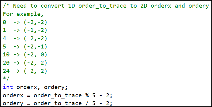
Here assumes we want to simulate 5 orders in x and y direction, so there should be totally 25 orders from (-5,-5) to (5,5). Because currently OpticStudio only considers the diffractive DLL simulates 1D grating, we need to represent the 2D orders in 1D. Here we will only consider orders from 0 to 24, which represents (-2,-2) to (2,2). If OpticStudio requests orders other than this range, we return -1, which will result in an geometric error in OpticStudio. For this reason, when using this DLL, the Start Order should be 0 and Stop Order should be 24 in OpticStudio.
Then, we can decompose the 1D order into corresponding 2D orders.
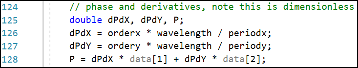
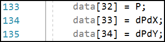
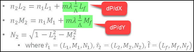
When data/31] = 1, we need to return the value for phase derivative and phase accumulation.
The phase (variable 'P') is simply accumulation of the phase assuming the phase at surfase vertex is zero.
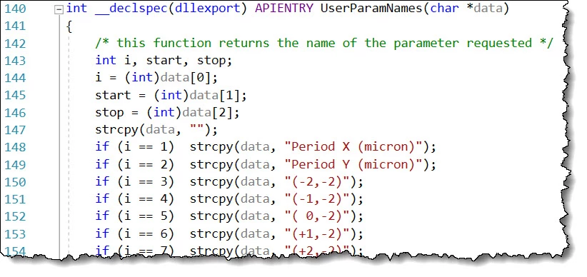
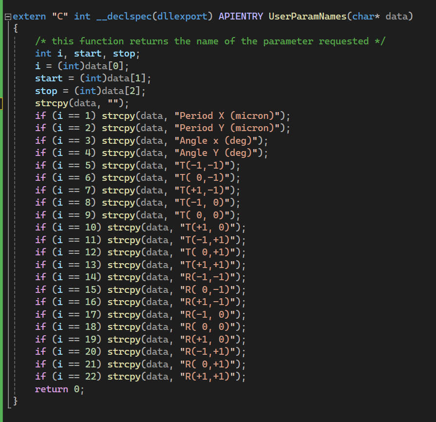
In UserParamNames(), we define the efficiency for each diffraction order.
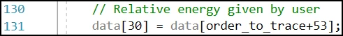
Then simply read it to datae30], which is the relative intensity reported to OpticStudio!
Page 1 / 1
Attached is a example for user defined surface used in sequential mode. This is modified from the built-in us_grate.c. The concept is same as above, but with one main difference: there need to be two parameters Order X and Order Y to let users explicitly specify what order to trace. This is because in sequential mode, only one path can be traced at once.
Only two parts are changed.
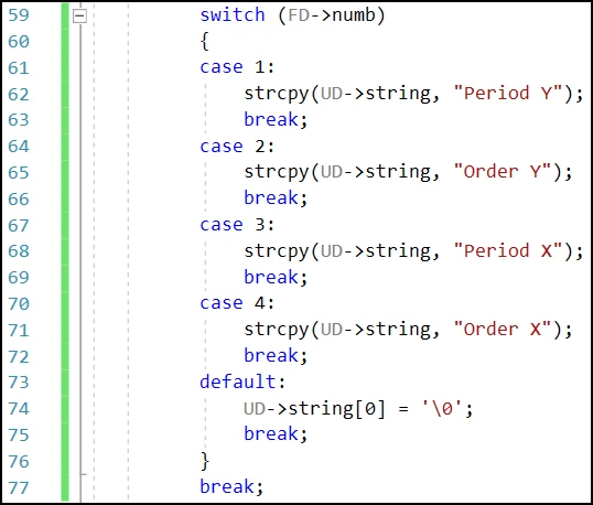
1. Add two parameters for x directional periodicity.
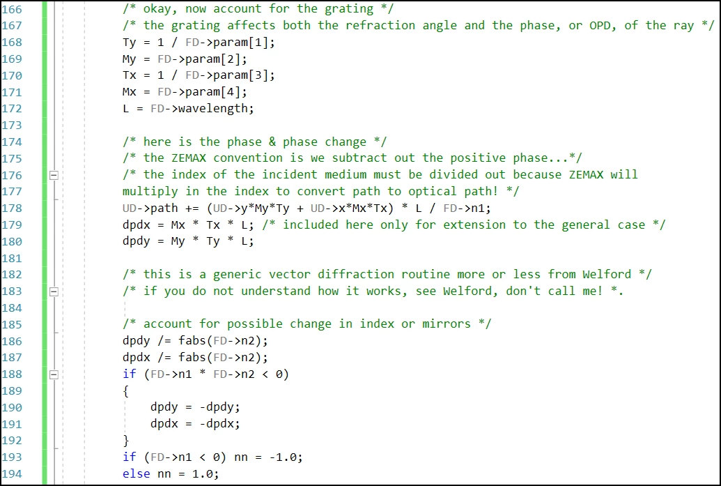
2. Code added to consider for another periodicity in x direction.
T,M becomes Tx,Ty,Mx,My.
Adding code for dpdx. Just mimics dpdy and that's it!
Gotta say Michael, you are doing some seriously good work here. Well done!
Hey Mark, that's great to see your reply and I'm glad you like it!
In OpticStudio, currently we only support one dimensional grating. However, it's not difficult to simulate 2D grating. Here we will show an example using diffractive DLL.
You may compile it with the instructions or use the DLL file attached to this article.
Before we start, here are some articles for required background knowledge that we will not repeat in this forum post.
Let's simply open the attached cpp file and observe how it works.
This example is mainly modified from the built-in sample \Documents\Zemax\DLL\Diffractive\diff_samp_1.c
To compile the program as C++ code. We package the functions with extern 'C'.
In this example, we only want to return diffraction ray direction and its relative intensity. So setting datat31] = 1 is enough. If we also know the polarization state or the full eletric field value, we can use data 31] = 2.
Here assumes we want to simulate 5 orders in x and y direction, so there should be totally 25 orders from (-5,-5) to (5,5). Because currently OpticStudio only considers the diffractive DLL simulates 1D grating, we need to represent the 2D orders in 1D. Here we will only consider orders from 0 to 24, which represents (-5,-5) to (5,5). If OpticStudio requests orders other than this range, we return -1, which will result in an geometric error in OpticStudio. For this reason, when using this DLL, the Start Order should be 0 and Stop Order should be 24 in OpticStudio.
Then, we can decompose the 1D order into corresponding 2D orders.
When data/31] = 1, we need to return the value for phase derivative and phase accumulation.
The phase (variable 'P') is simply accumulation of the phase assuming the phase at surfase vertex is zero.
In UserParamNames(), we define the efficiency for each diffraction order.
Then simply read it to datah30], which is the relative intensity reported to OpticStudio!
Hi,Michael!
I meet a problem that when setting datar31] = 2 in the built-in sample \Documents\Zemax\DLL\Diffractive\diff_samp_1.c and output the new DLL , Diffraction Grating with the new DLL in which datat31] = 2 can not receive beam rays, namely the light beams can not reach the diffraction grating.
Why it become like this?
Looking forward to your reply! Thank you !
zhouqing
Hi Zhouqing,
Thank you for reply. Setting data[31] = 2 should be not a problem. The problem probably happens at your other code. Could you send your question to support inbox so we can help to further look at your question? Thank you!
Michael
Hi Michael! Thank you very much for your reply!
I have send my question to the mailbox Zemax Community <community@zemax.com>. In case of encountering problems when sending the email,I also present my questions in more detail as below:
Firstly, I just change the code data<31] = 1 to datao31] = 2 in the built-in sample \Documents\Zemax\DLL\Diffractive\diff_samp_1.c and output the new DLL.
When I use the new DLL in Diffraction Grating in NSC mode, the light beam can not reach the grating. Maybe there are something wrong when I changed the code in the built-in sample \Documents\Zemax\DLL\Diffractive\diff_samp_1.c.
Then I review the DLL in ZEMAX Knowledgebase(KBA), there are some keys as shown below:
According to the above content, If I set the code data 31] = 2 , then the data535]~"37], and data p40]~e45] should also be calculated or set. For the further code setting of dataa35]~b37] and data o40]~t45] , I still feel a bit difficult to input the perfect new codes as I am not familiar with the C++ and ZEMAX Programming logic for Diffractive DLL.
If Michael could give me some help or suggestions for the above tricky situation as I meet.
Looking forward to your reply! Thank you!
Zhouqing
Hi Zhouqing,
I’m sorry for confusion, but could you try to create a case via the following link.
Both method will reach to the same team. Using the link is suggested as you will be able to check the status of the tickets. Please note you will need to create a Zemax account in order to open a ticket. Please let us know if you have any issue. Thank you.
At the same time, I also present my questions again as below:
I just change the code data>31] = 1 to data�31] = 2 in the built-in sample \Documents\Zemax\DLL\Diffractive\diff_samp_1.c and output the new DLL.When I use the new DLL in Diffraction Grating in NSC mode, the light beam can not reach the grating. Maybe there are something wrong when I changed the code in the built-in sample \Documents\Zemax\DLL\Diffractive\diff_samp_1.c.
Then I review ” Custom DLLs in OpticStudio: An overview of user-defined surfaces, objects, and other DLL types”in ZEMAX knowledgebase (KBA), there are some keys as shown below:
“ If data=31] equals 2, it must also calculate data 35-45, the complete output ray data. The DLL should return 0 if successful, and -1 if it encountered an error. For a complete description of all the data items passed between ZOS and the Diffraction DLL, please see the example {Zemax}\DLL\Diffraction\diff_samp_1.c.”
“Note when the data"31] is 2, the power of diffracted ray is mainly calculated by the returned field data in datae40-45]. However, the dataa30] can still affect the ray-tracing in two ways. One is that OpticStudio will use dataO30] for estimating the Lost Energy, which shows in the Ray Trace dialog, during raytracing. One is that the diffractive ray will stop tracing if the value in datai30] is smaller than Minimum Relative Ray Intensity in the System Explorer.
According to the above content, If I set the code datas31] = 2 , then the data�35]~d37], and data �40]~>45] in the built-in sample diff_samp_1.c should also be calculated. For the further code setting of datae35]~c37] and data h40]~r45] , I still feel a bit difficult to write the perfect new codes as I am not familiar with the C++ and ZEMAX Programming logic for Diffractive DLL.
If Michael could give me some help or suggestions for the above tricky situation as I present.
Looking forward to your reply! Thank you!
Zhouqing
Thanks for the tutorial Michael, very informative.
I have tried to implement a similar code that the one you provide here but to also analize the reflection modes of a simple 2D grating. In my case I restricted the Tranmission and Reflection modes to (-1,-1) → (1,1).
In my case the call for input parameters looks like this:
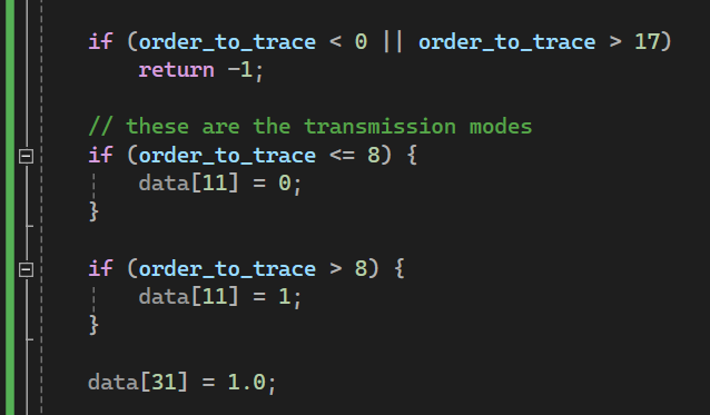
I have tried to modify datai11] value to accomodate either tranmission and reflection modes asking which mode is being calculated as follows:
but this proven not to work. Zemax only calculated the transmissive modes and all the reflection modes are there but as simple reflection from a glass surface.
Could you please give me a hint on how to implement this properly?
Thank you!
Hi, Michael.
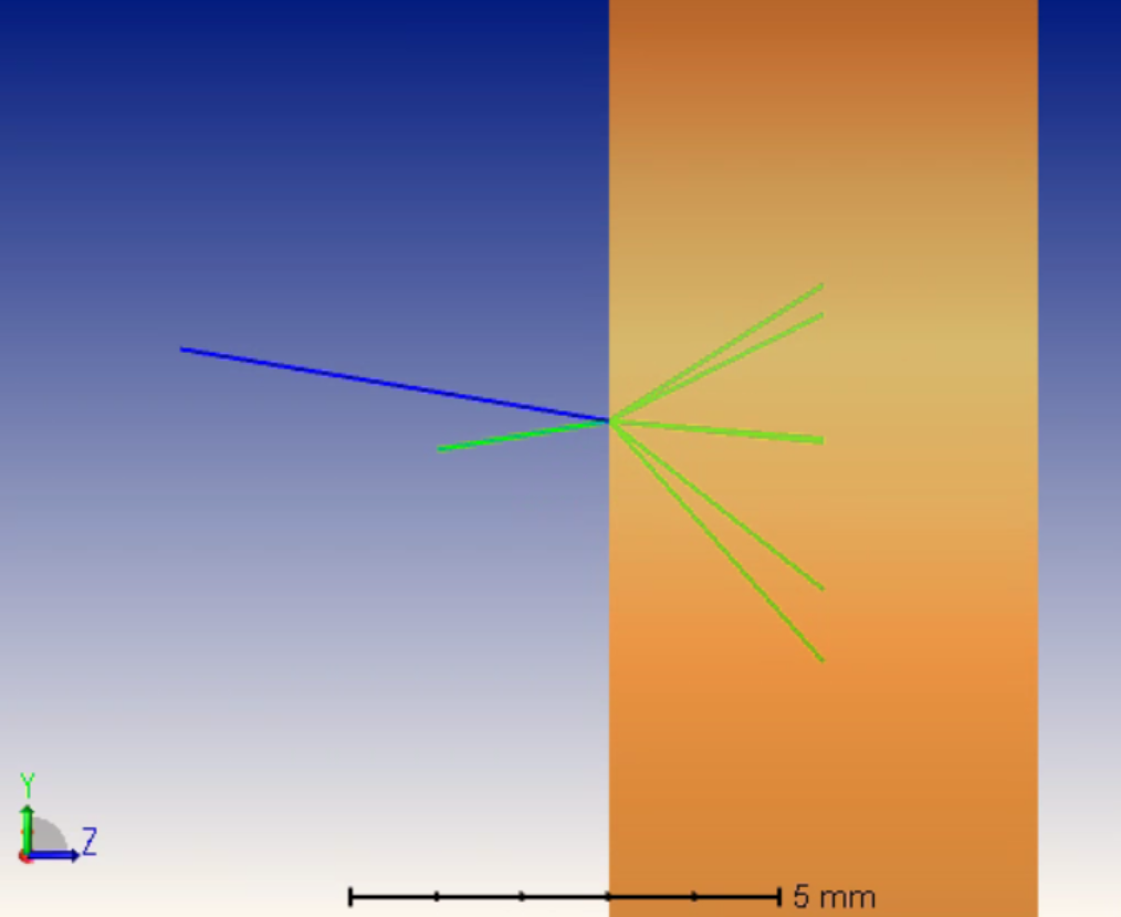
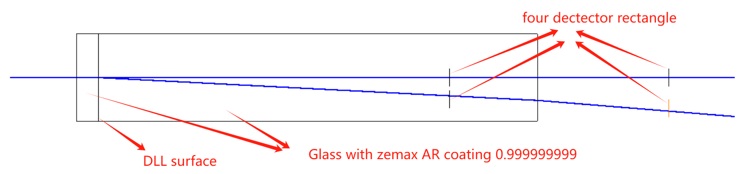
Thanks for your input to the community. I am wondering how the zemax calculate the power of ray, which comes out of the DLL surface (RCWA model for a grating). In the DLL, data [30] represents relative energy of the ray. Here I assum it is diffraction efficiency, which is power flow. Besides, the output electric is also required to give in data [40-45]. Based on my test, the zemax detector seems to calculate the energy of the ray from DLL based on its square module of electric field instead of diffraction efficiency. However, when the diffraction efficiency of first order of light is high, e.g. 99.9%. The square module of electric field is usually larger than 1 because the k-vector changes. Therefore, I have normalize the electric field and multiple square root of the diffraction efficiency to achieve the right number on detector, which is contradictory to the law of wave propagation. Besides, If I did this, the detector energy will change again when this ray from DLL interact with next surface, which is a glass usrface with perfect AR coating. . Do you know what is happening?
Here is my setup. The power on detectors inside glass is 99.941%, which is exactly same as the diffraction efficiency. The power on detector outside of glass is 99.864%. I also tested the AR coating. It is perfect for different incident angles and impossible to influence such 0.1% power variation.
Hi Yuqiang,
I feel there are some specific problem in your code and the test. It’s probably best you send your question through support so we can look into details to know the exact issue. However, I guess the following principles can be useful.
It’s correct OpticStudio uses s40-45] for the power of the ray not datad30], when datad31] is 2. However, you should still make sure datad30] = sum(datad40]^2+datad41]^2+...datad45]^2)_output / sum(data(40]^2+data+41]^2+...data.45]^2)_input.
The electric field should be perpendicular to ray direction. Namely, when you return data, you should make sure datae4]*data]40]+data]5]*data]42]+data]6]*data]44]=0 and datad4]*data441]+data15]*data543]+data36]*data645]=0
Hope these are useful information.
Thanks, Michael.
I will check one by one. Could you share how zemax calculate the energy of ray at different scenarios? It looks like zemax will use relative energy in some situations, but use inner product in other situations.
Best,
Yuqiang
Hi Yuqiang,
Do you mean dataa30] by relative energy? As discussed above, when dataa31] is 2, it’s not used as ray power, but it will be used for judging whether a ray should stop trace because of too low level of power. You can check the following article.
Otherwise, I think it works as you expect where it changes the ray power.
Thank you for your insights, Michael.
I’m currently working on speeding up the DLL computation for diffractive optical elements. As we know, the RCWA model calculates the electric field and efficiency for each diffraction order (both transmission and reflection) in a single call. However, the current DLL template can only extract one order per call, requiring multiple redundant calls to retrieve, for example, the ±1 and 0 orders. This results in significant slowdowns—at least 6 times slower—due to repetitive calculations.
While this inefficiency is manageable for volume gratings (intensity or polarization type), which typically need only 3–5 harmonics for accurate RCWA results, surface relief gratings (SRG) often require over 50 harmonics. Repeating the process for each order wastes considerable computational resources, especially during optimization.
Do you have any suggestions for modifying the DLL to output multiple diffraction orders in a single call, thereby reducing computational waste?
Hi Yuqiang,
Unfortunately, currently the interface will always call the DLL for each of harmonic orders. However, I think it’s usually not a major problem. If you have many orders to return, I think we should not really send out rays for all orders. If you do so, it means one ray is split into, for example, 50 rays. If 10 of these rays go back to the grating, they are further split into 500 rays. You will soon reach the limitation of segments and the simulation gets very slow. My suggestion would be you only set one diffraction order by using Start/Stop X/Y = 0, and in the DLL you will randomize the output based on output ray power. These are quite complicated programming task. If you have difficulty to do this, I would also suggest you describe what kind of application you want to do and see if we can consider this in the product feature. Thank you!
Dear Michael,
Thanks for your response. We are doing some waveguide displays with heavily interaction bettewen DLL (or BSDF file) and ray tracing. DLL-based BSDF could also accelerate the simulation speed. Could you give me some info (or an example) for building our own DLL-based BSDF?
Best,
Yuqiang
Hi Yuquiang,
I think this is probably a little more than a question for the community. If possible, could you share your question to either channel partner or support system via Zemax?