I want to model a micro-lens array in NSC mode (clear aperture < pitch). I tried to use normal lens and array, but this create an array of lens with cylindrical sides (the space between two adjacent lenses is air) which will introduce TIR when AOI of rays exceed critical angle. In real case, the micro-lens array has one side flat and the other side an array of aspherical lenses with circular clear aperture, the substrate of the micro-lens array is a continuous slab so TIR won't happen between neighboring lenses (the space between two adjacent lenses is the lens substrate). How could I model the real case more accurately so TIR won't happen when light enter from one lens to the neighboring lens? I initially tried to use the lenslet array 1, but it has rectangular-shaped lens which is also not the same as what I want to model. 

One additional option would be that if you had a very regular pattern of parent objects with different coatings, you could have more than one array of objects and then space the arrays such that they are flush with each other. This would create functionally a single array, but with repeating patterns of properties such as coatings.


Hello, 

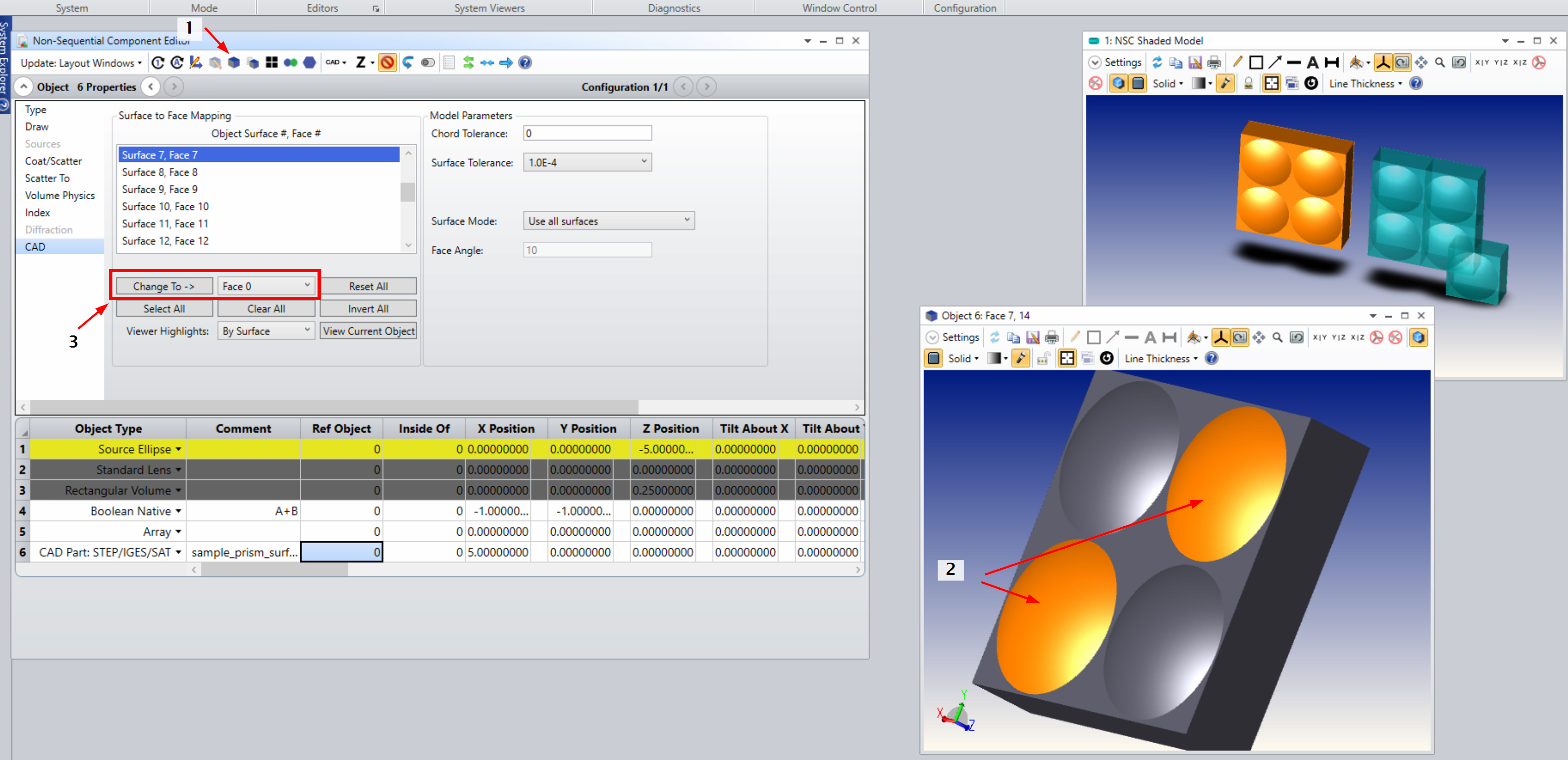
In case you don’t need to change the geometry of the lenslet array anymore and you need to assign different coatings to different lenslets, you could export it to a CAD file and then add it to your model as a “CAD Part”. This will allow you to remap individual surfaces of the object to “Faces” (Face 1, Face 2 etc.) to which you then can assign coatings as you wish. 

See the screenshot below: 

  1. select the new CAD part (Obj 6 in my screenshot) and open the Object viewer (arrow 1)
  2. Open the Object properties and go to the CAD section. Then select the surfaces you want to “group” in the object viewer (arrow 2). The selection will be automatically updated in the object properties dialog.
  3. in the object properties you can then remap the selected surface to a specific Face by clicking “Change To ->”. This face can then be used in the “Coat/Scatter” settings


This should work. Maybe there is a smarter or more convenient way, if so please feel free to post it 😉


Good luck & hope this helps, 

Daniel


Hi Sean,

Thank you very much for sharing you approach in a clear step by step way. Very helpful. One more question is regarding the coating setting. I found the combined objects could have many faces and in the case I need to assign various coating properties to different faces, I found it tedious to do it over and over one by one. I am wondering whether there is a way to group faces with the same coating properties so next time when I change I could just change the coating for the entire group instead of having to go over one face at a time (also easy to make mistakes).

Any advice on this?

Thanks very much.


Hello,

I am currently modeling a microlens array like this, and here is my solution using boolean operations. I would like to hear if there are other approaches.

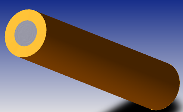
First I created a standard lens object. This allows me to create the aspheric surface with the circular clear aperture I desire. Edge radius is oversized at this point to allow for boolean addition later. Length is equal to the thickness of the microlens array substrate.


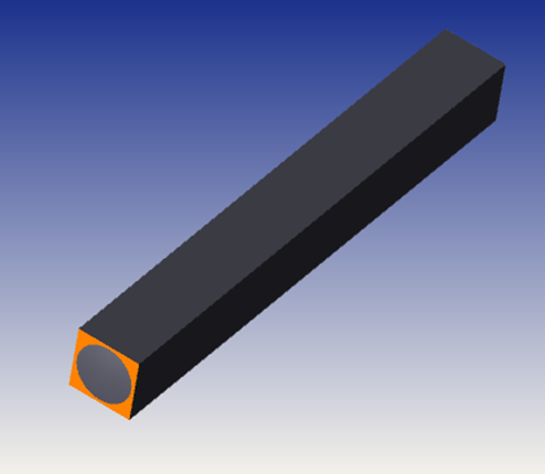
Next I created a rectangular volume to define the X and Y pitch of the individual element. This should fit inside the cylinder from step 1. Z length for the rectangular volume should be at greater than or equal to the length of the first object.

Then comes the Boolean Native with operation A&B to combine the two. This should leave you with a rectangular object, with a convex surface and circular aperture smaller than the square face. 

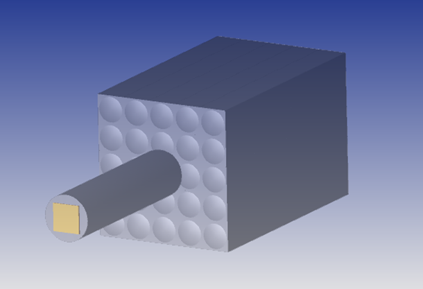
The final step is to use an Array object with the Boolean Native object as the Parent Object. Below I have the rectangular volume highlighted, shown inside the standard lens. Behind them is a 5x5 array of the boolean native object. 

I hope that helps.

-Sean


Reply