Solved

Distortion and Vignetting

  • 1 December 2021
  • 7 replies
  • 1898 views

Hi all,


What is the correct way to analyze distortion in a system?
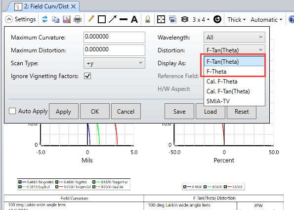
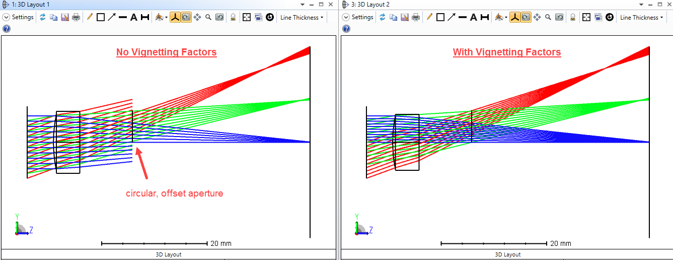
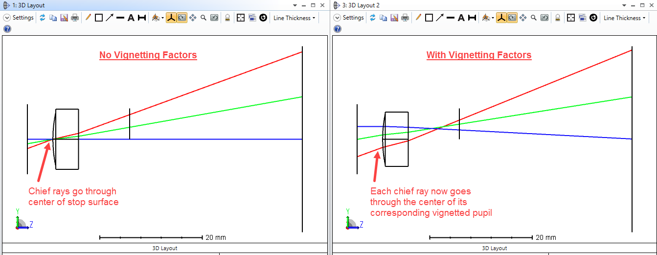
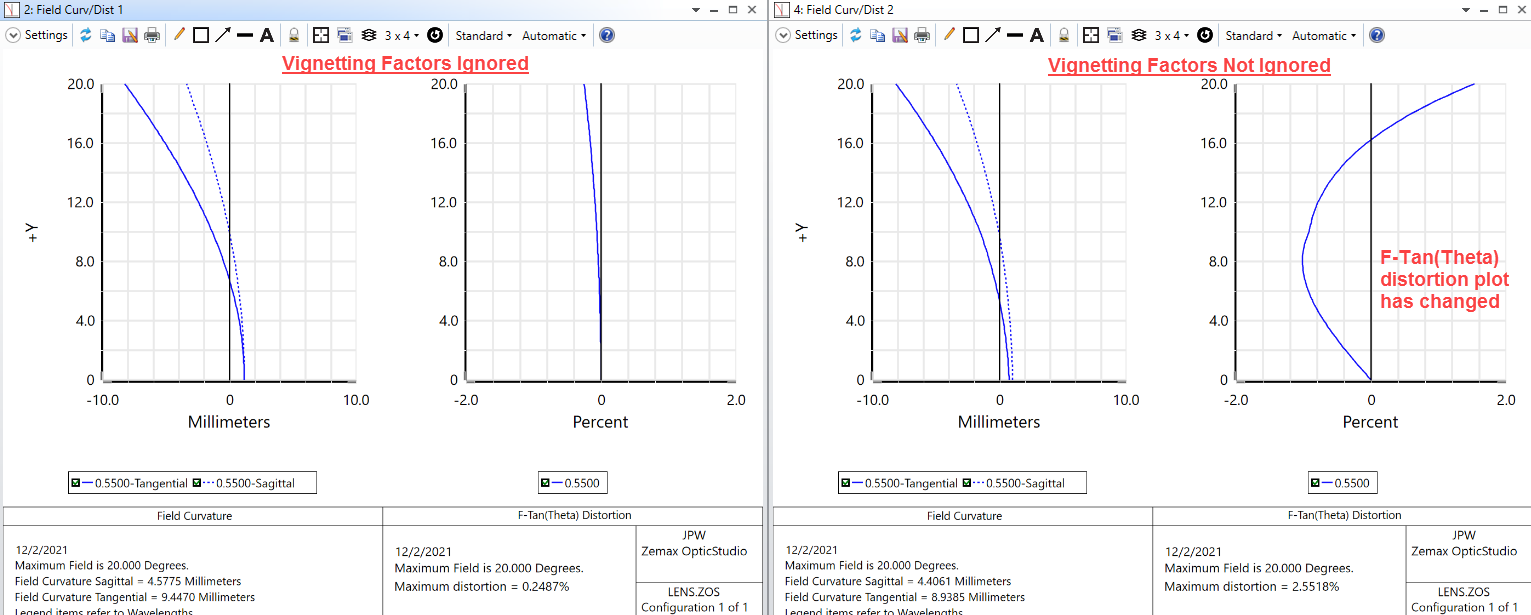
At the settings in “Field Curv/Dist” plot there is an option to tick/untick “Ignore Vignetting Factors”.
In several cases I noticed that I achieved quite different results between the options and I wonder how to relate to it.
Which of the options represents a more credible result?
Also, are there different cases that require to use each option individually or there is some general consent?
If different cases require different method, then why and what should be the guideline?


Thanks,

Ziv

icon

Best answer by Jeff.Wilde 2 December 2021, 19:49

View original

7 replies

Userlevel 7
Badge +3

Most wide-field imaging lenses produce significant distortion.  The “Field Curv/Dist” analysis window quantifies the effect by plotting the percent difference between the landing position of the actual rays and corresponding reference locations.  The two most commonly used reference positions are calculated as: F-Tan(Theta) or F-Theta.  The first one corresponds to an ideal imaging lens with no distortion, while the second one provides the difference relative to a typical ideal scan lens in which the goal is to have F-Theta distortion (so the focused spot scans the image plane linearly with changes in the incoming field angle). 


You don’t need to worry about vignetting factors unless you have specifically set them to non-zero values.  If the vignetting factors are all zero (their default values), then checking or unchecking the box makes no difference.  In imaging systems in which apertures other than the stop clip rays, then vignetting factors can be used to modify the way rays are launched so as to avoid this clipping (and hence modify the way the pupil is filled).  You can read more in the corresponding help section.

You may also want to look at the Grid Distortion feature.  Here are results from the “Wide angle lens 100 degree field.zmx” example file:


Hi Jeff,


Thanks for your elaborated answer.
In my question I referred to the second case you mentioned where the vignetting factors are not zero.
I determine my vignetting factors by locking the clear semi-diameters in LDE and then use the automatic tool ‘Set All Vignetting’ in FDE (then release lock and return to ‘automatic’ for the semi-diameters in LDE).
I still do not understand why there is such difference in distortion results between ignoring/not ignoring vignetting factors.
As I understand it, if I do not ignore the vignetting factors, so all the rays that are not clipped will be launched and accounted for the analysis.
Otherwise, if I do ignore the vignetting factors, then all rays will be launched, but in the way some of them will be clipped anyway by some apertures in the system and eventually will not reach the image plane for analysis. So why does it matter?
Unless the automatic tool I used for set vignetting is not accurate enough.

Do I understand it correctly? If not, what am I missing?


Thank,

Ziv


Userlevel 7
Badge +3

Hey Ziv,

Vignetting factors are defined for each field point, whereas the distortion scan uses field as a continuous variable. OS will interpolate the VFs for an arbitrary ray using the two closest field points values. My preference is to turn them off, especially if you only have a few field points.

  • Mark
Userlevel 7
Badge +3

Hi Ziv,

To expand on Mark’s point, here’s a simple example. 

Consider a plano-convex imaging lens (0, 10 & 20 degree field angles) with the stop surface set as the first lens surface. Add an external offset aperture behind the lens, and then look at ray tracing without vignetting factors compared to with them:

Since distortion is computed relative to chief ray positions in the image plane, it’s of interest to look at only the chief rays:

It is clear that they take different paths depending on whether or not vignetting factors are utilized.  As a consequence the distortion plots are different:

Which version is more relevant for your application is up to you.  As Mark noted, because of the implementation, if you prefer to include the vignetting factors then it’s probably best to add more field points to improve the interpolation.

Jeff


Userlevel 7
Badge +3

That’s a great explanation Jeff! Indeed, the reason the feature is selectable is that the user does need to decide this. As a design matures, I like to shift all definitions to be ‘object sided’, remove VFs and use hard apertures instead, and increase the aperture slightly so the pupil is overfilled with rays. While this is wasteful in that you trace rays that don’t get through, it is physically realistic.

  • M
Userlevel 7
Badge +3

Thanks Mark.  I agree, you typically can’t go wrong (post optimization) by overfilling the stop and turning off VFs as long as the loss of all the clipped rays is computationally tolerable.  On occasion, I encounter a situation where a small external aperture is needed for one reason or another, and then using VFs is very helpful, but that’s more of an exception than a rule.

That being said, I just took a look at a good KB article by Sanjay on the use of VFs: 

How to use vignetting factors

He points out that if vignetting is present, it’s best to use VFs during optimization so that Gaussian Quadrature pupil sampling can be utilized.


Thanks a lot Jeff and Mark!

Your answers and explanations helped me to understand it better and also realize what OS does in order to decide which version to implement in different situations.


Ziv


Reply