Building Exit Pupil Expansion (EPE) based volume holographic gratings (VHG)

  • 17 October 2021
  • 9 replies
  • 1115 views

Userlevel 6
Badge +2


In the following article, we introduced how to build an EPE based on surface-relief grating (SRG). However, this does not work for holographic gratings.

How to simulate exit pupil expander (EPE) with diffractive optics for augmented reality (AR) system in OpticStudio: part 1

The current available Kogelnik model in OpticStudio cannot be used for EPE waveguide. Here we will explain why and provide a workaround DLL. 

Note this is based on assumptions and the result could be inaccurate.

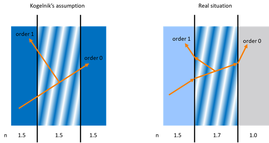
In Kogelnik’s method, it assumes, as below, that the refractive index of the hologram itself and its environment are same. Even after the hologram fringes are developed, the average refractive index is still same.

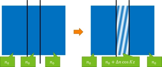
However, in reality, the refractive index from the environment is different.

For example, we might have a hologram, with average refractive index of n0 = 1.5, coated on a glass substrate, with refractive index of n1 = 1.7. And the other side is AIR, with refractive index of n2 = 1.0.

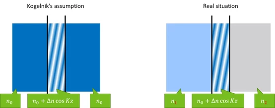
In real situation, the ray behavior will be a little different. You can imagine the rays need to be refracted at the boundary as shown in the right picture below.

Note this it NOT exactly what happens in the hologram, but it’s a very intuitive way to explain. And it’s roughly correct.

So now the problem is this means sometimes the ray can see TIR condition and can not leave the hologram zone. You can see the order 0 in the right side in following picture.

In Kogelnik method, the power of this TIR ray is undefined. In the DLL and the native implementation in current OpticStudio, we simply stop tracing rays in this case.

Normally, the holographic grating is rarely used in this way and we won’t have problems. However, for EPE waveguide applications, this is a very common case.

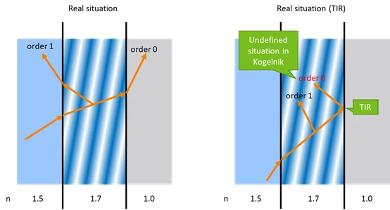
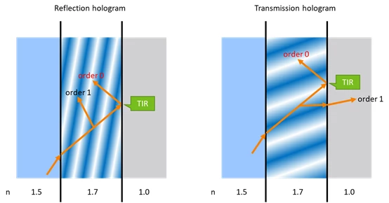
Note, not only reflection hologram, this can happen to transmission hologram too.

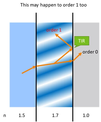
And it could happen to order 1 too.

In attached ZAR file, we have used two assumptions to make the DLL also working for TIR conditions.  Note users should set the waveguide mode to non zero in order to turn the feature on. The two assumptions are:

  1. If the order 1 ray does not exist, the order 0 takes all power.
  2. If the order 0 ray encounters TIR condition, it goes reflection direction.

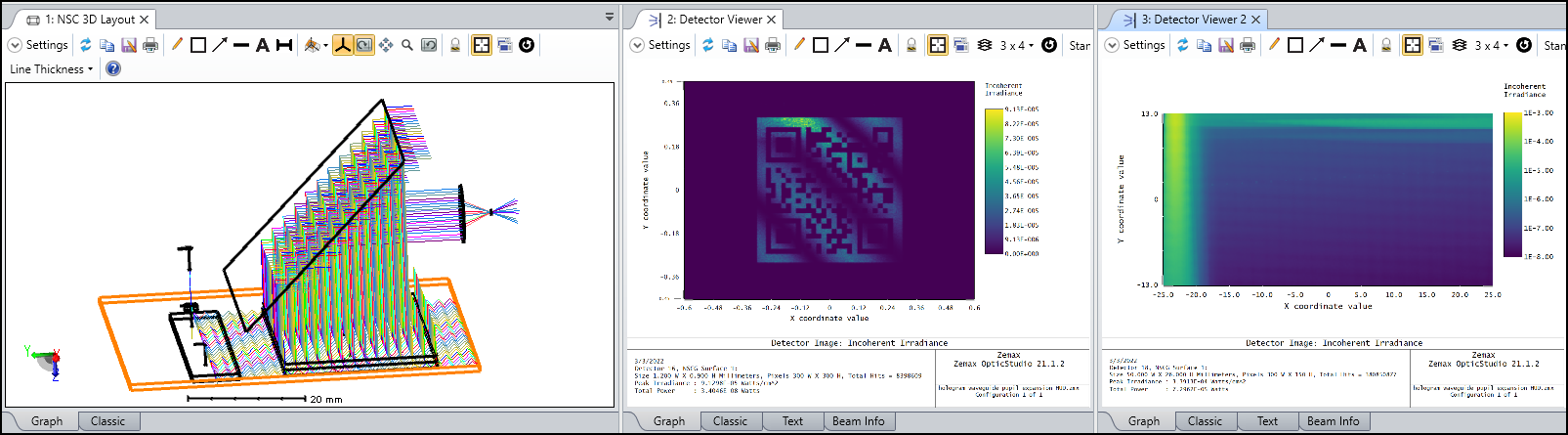
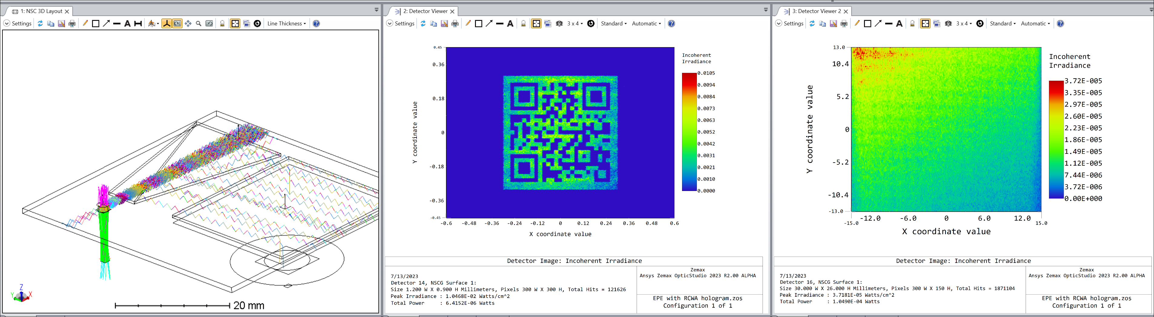
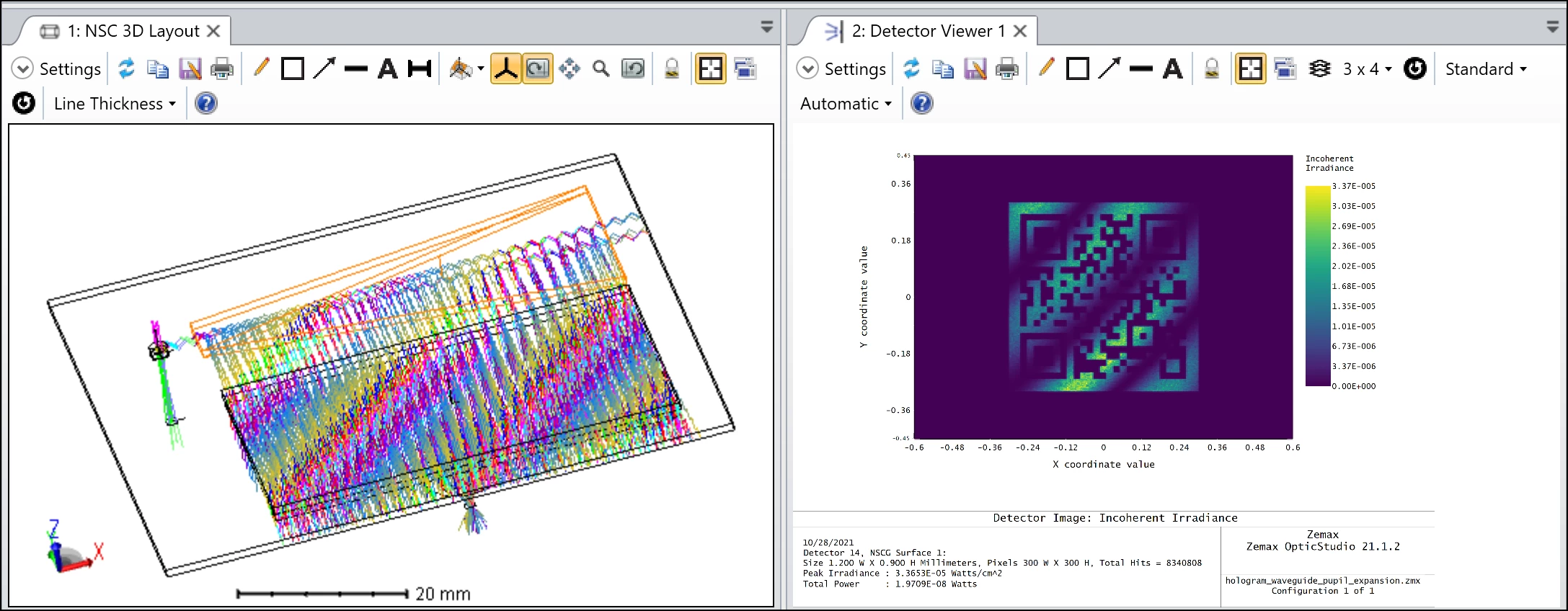
The system works as below.


By opening this ZAR file, the workaround DLL will be extracted to the correct folder.

Note this DLL has a few restrictions:

  1. The DLL is only a workaround and it works with some assumptions. The result could be inaccurate. Readers should check the theories and the assumptions.
  2. This DLL is locked to subscription license.

For more general information about Kogelnik model in OpticStudio, readers can refer to the following article:

Simulating diffraction efficiency of a volume holographic grating using Kogelnik’s method


9 replies

Userlevel 6
Badge +2

Attached is a slightly modified example to demonstrate how it looks like if we simulate it as an HUD system.


Hi Michael,

Thank you for your post! That is very helpful!

And I have some questions:

1. The new DLL not only uses ACWA (Kogelnik’s method) to simulate diffraction efficiency vs angle & wavelength, but aslo takes 0th other into consideration, does that mean for certain angular domain where the maximum diffraction efficiency is 100%, then there is no 0th order that will TIR inside waveguide, is it correct?

2.In the new DLL, does all the parameters have the same unit as the built-in ‘Hologram Object (like hologram lens)’ in Zemax non-sequential mode?

Thank you again!

Best,

Kaden

Userlevel 6
Badge +2

Hi Kaden,

Thank you for reading this.

  1. Yes, that is how exit pupil expansion normally works. We let rays propagate via TIR in the waveguide and diffract rays to break the TIR with (holographic or surface-relief) gratings.
  2. All the “length” related parameters should be in unit of mm unless we specifically mention in the parameter name. Also whenever you set up wavelength in OpticStudio, it’s always in micron, unless we specifically mention in the parameter name.

Please let me know if you have any more questinos!

Michael

Hi Michael,

Thank you for your reply! I understand the principle of pupil expansion is to use a larger size of out-coupler to accommdate multiple diffraction and TIR to increase eye-box.

But my following question about its modelling in Zemax is, for example, when the TIR angle of the ray bundle propogating inside waveguide (glass n=1.5) is between 50 to 54 degrees, when such ray bundle firstly hits onto the out-coupler, it is designed to achieve 100% diffraction efficiency (according to ACWA) within the mentioned angular domain 50 to 54 degrees, then since all the beam is diffracted out of the waveguide, the ray bundle in that angular domain will not continusly TIR inside waveguide, then actually, there should be no pupil expansion specifically for this angular range, am I correct?

I try to use the new DLL to simulate, but I found the ray bundle within the mentioned angular range can still TIR insied waveguide, could you please provide me some insights?

Thank you!

Best,

Kaden

Userlevel 6
Badge +2

Attached is a system that use RCWA for hologram modeling.

The key difference to what we originally shared in this article is this DLL uses RCWA instead of Kogelnik to calculate the diffraction. Consequently, it supports fully multiple order of diffraction and accurate consideration of environment material at two sides of the grating.

Many parameters have the same definition as described in Simulating diffraction efficiency of surface-relief grating using the RCWA method – Knowledgebase (zemax.com) and Simulating diffraction efficiency of a volume holographic grating using Kogelnik’s method – Knowledgebase (zemax.com).

Note one important difference is this DLL only supports collimated construction beams and not point construction source. The X1,Y1,Z1,X2,Y2,Z2 are always multiplied by a large number in the code, which means they are a point source at infinity.

How do you do the Diffraction efficiency analysis here?

if these are volume holograms i should be able to see the wavelength and angular selectivity plots. Also, i should be able to vary refractive index modulation values so that i can vary diffraction efficiency for achieving uniform intensity in exit pupil. How does your model support that?

Userlevel 6
Badge +2

HI Branavreen,

You can build up a test system and run the test you need. You can follow the examples in the following two articles to run this test.

Simulating diffraction efficiency of a volume holographic grating using Kogelnik’s method – Knowledgebase (zemax.com)

Dynamic workflow between Lumerical RCWA and Zemax OpticStudio – Knowledgebase

Please let me know if you have any questions in the article. Thank you.

I have developed a system in NS mode where I am attempting to do 2D pupil expansion by using multiple re-directions and extractions. I am using segments of hologram lens placed adjacent to each other with varied diffraction efficiency (by calculating refractive index modulation for particular DE using Kogelnik’s theory). Despite using the theoretically calculated values, I am unable to get uniform output on the detector after the exit pupil. I am using ray splitting with rays having much lower minimum intensity. As you said for EPE DLL should be used. the pupil is expanded in my system but the intensity is not coming out to be uniform. Can uniformity be achieved in my system? or i have to use DLLs. I wouldn't prefer the latter system because it seems bit complicated to me. 

Userlevel 6
Badge +2

Hi Brarnavreen,

For an exit pupil design, we have an optimization example available here: Optimization of an Exit Pupil Expander with 1D gratings – Ansys Optics. In this example, we use an SRG, but I think it’s similar principle for a VHG design.

If you still have question specific to your system, I would suggest you send the message to zemax.supoprt@ansys.com and we should be able to have more look for you.

Hope this is useful. Thank you!

Reply