In this post, it’s introduced how to simulate realistic grid wire polarizer with RCWA function that comes with OpticStudio 20.2.
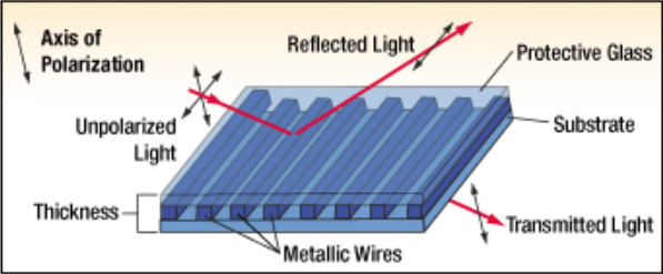
(Source: https://www.thorlabs.com/newgrouppage9.cfm?objectgroup_id=5510)
Note there are many different types of polarizer
- For polarizer based on birefringent crystal, check the following article: How to design birefringent polarizers
- For polarizer based on coating, there is no an article specific to introduction, but users can refer to the following article to know how to set up a coating and assign to object for beam splitting: How to model a dichroic beam splitter
- Then it’s also worth to note the existence of a build-in ideal coating “PASS_P”. This coating allows P polarization to pass and reflect light with S polarization.
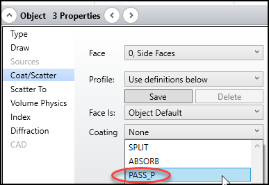
Note the coating method can only work for obliquely incident beam. Usually this kind of polarizer is made as a cube or a plate oblique placed in the system. More information can be found in this forum post: 'Pass_P' coating fail for the modeling of a wire grid polarizer, how to model it correctly?
Back to Grid Wire Polarizer
In past, the grid wire polarizer was mainly simulated with Jones Matrix or DBEF, which are ideal models.
How to model a Dual Brightness Enhancement Film
How to use the Jones Matrix surface
Since OpticStudio 20.2, a new diffractive DLL called “srg_gridwirepolarizer.DLL” for accurately handling this kind of polarizer is added. This DLL is based on RCWA algorithm. More about RCWA can be found in the following article: Simulating diffraction efficiency of surface-relief grating using the RCWA method
To demo how to set up an accurate grid wire polarizer model with this DLL, a sample file is attached in this forum post. In the sample file, it can be seen the system is set up as below.
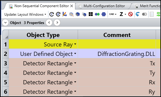
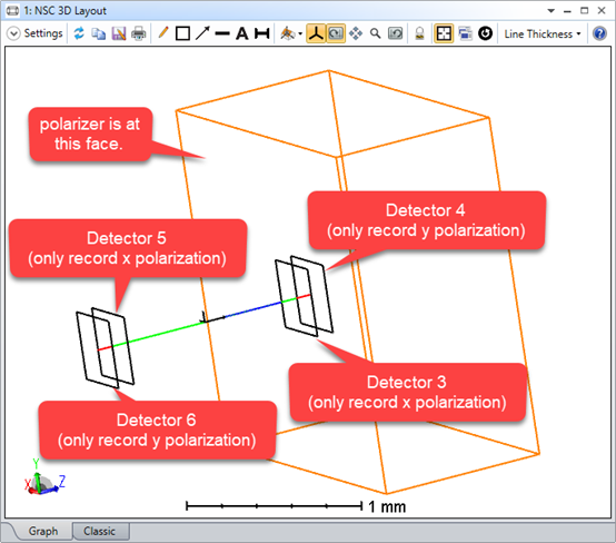
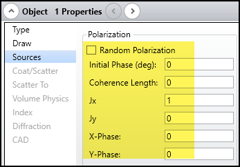
Object 1 is a source that will always send one ray in z direction. By looking at Object Property > Sources, it can be seen the source is y-polarized.
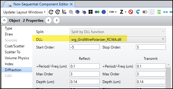
Object 2 is a User Defined Object reading the DiffractionGrating.DLL. This object’s first face is diffractive and set with the “srg_gridwirepolarizer_RCWA.dll”. This DLL can simulates binary grating. A grid wire polarizer here is simulated as a binary grating but period much smaller than light wavelength and the material being metal (n = 0.7-7i).
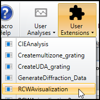
The shape of the grating can be checked with the tool User Extension > RCWA_visualization.
By clicking “Draw”, the geometry of the grid wire polarizer can be shown as below.
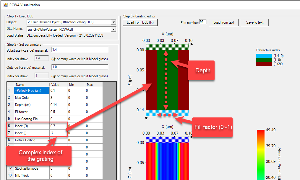
The meaning of the parameters is explained in the above picture. The grating direction is along the y-axis and can be changed by Rotate Grating parameter.
Again, more information about this tool can be found in the knowledge base article: Simulating diffraction efficiency of surface-relief grating using the RCWA method.
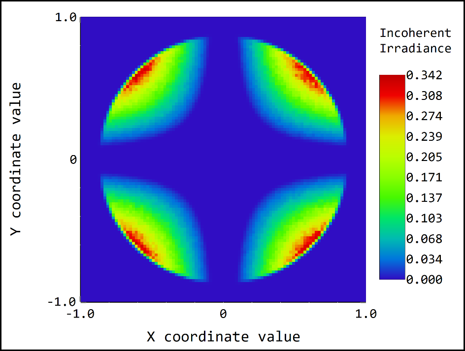
In the sample file, there are 4 Universal Plot draws the energy received by the 4 detectors. In the plots, the incident light’s polarization state is rotated.
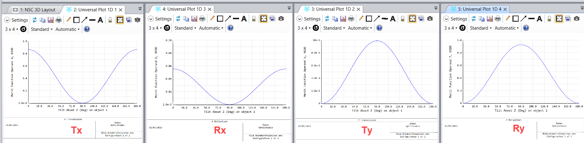
It can be seen, at x = 0, Transmit X = 85%, Reflect X = 7%, Transmit Y = 0%, Reflect Y = 0%
And at x = 90, which means ray is incident with exact x polarization:
Transmit X = 0%, Reflect X = 0%, Transmit Y = 0%, Reflect Y = 93%